
EM78P312N
8-Bit Microcontroller
36
•
Product Specification (V1.0) 10.03.2006
(This specification is subject to change without further notice)
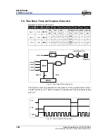
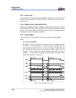
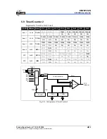
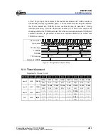
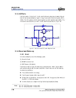
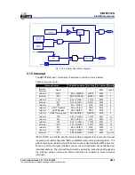
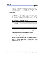
5.9.1 Timer
Mode
In Timer mode, counting up is performed using the internal clock. When the contents of
the up-counter matched with the TCR2 (TCR2H+TCR2L), then interrupt is generated
and the counter is cleared. Counting up resumes after the counter is cleared.
0
1
2
4
n-1 n
1
2
3
Internal clock
Up-counter
5
TC2 interrupt
0
n
match
counter
clear
TCR2
n-2
n-3
3
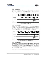
Fig. 5-19 Timer Mode Timing Chart
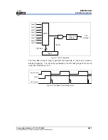
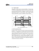
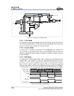
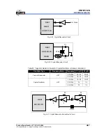
5.9.2 Counter
Mode
In Counter mode, counting up is performed using the external clock input pin (TC2 pin)
and
either rising or falling
can be selected by setting TC2ES. When the contents of
the up-counter matched with the TCR2 (TCR2H+TCR2L), then interrupt is generated
and the counter is cleared. Counting up resumes after the counter is cleared.
0
1
2
3
n-1 n
1
2
3
TC2 Pin
Up-counter
4
TC2 interrupt
0
n
match
counter
clear
TCR2
n-2
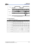
Fig. 5-20 Counter Mode Timing Chart (TC2ES = 1)
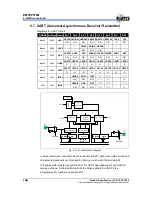
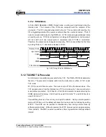
5.9.3 Window
Mode
In Window mode, counting up is performed on the
rising or falling edge
of the pulse
that is logical AND of an internal clock and the TC2 pin (window pulse). When the
contents of the up-counter matched with the TCR2 (TCR2H+TCR2L), then interrupt is
generated and the counter is cleared. The frequency (window pulse) must be slower
than the selected internal clock.
Writing to the TCR2L, the comparison is inhibited until TCR2H is written.