5.
Open
the
blade
server
cover
(see
“Opening
the
blade
server
cover”
on
page
20
for
instructions).
6.
If
you
are
installing
a
DIMM
in
the
blade
server
and
an
expansion
unit
is
attached
to
the
blade
server,
remove
the
expansion
unit
(see
“Removing
an
expansion
unit”
on
page
21).
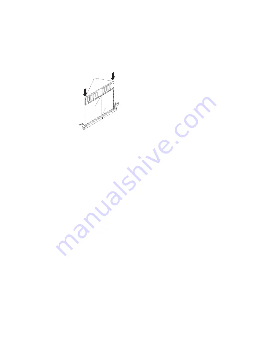
The
following
illustration
shows
how
to
remove
and
install
a
DIMM.
This
illustration
also
applies
to
removing
and
installing
a
DIMM
filler.
Press evenly
at arrows
Tab
Notch
7.
To
install
the
DIMMs,
repeat
the
following
steps
for
each
DIMM
that
you
install:
a.
Locate
the
DIMM
connectors
(see
the
illustrations
in
“Blade
server
connectors”
on
page
16).
Determine
the
connector
into
which
you
will
install
the
DIMM.
b.
Remove
the
DIMM
filler
from
the
DIMM
socket.
Note:
If
a
DIMM
is
not
installed,
a
DIMM
filler
must
occupy
each
DIMM
socket.
c.
Be
sure
that
both
retaining
clips
on
the
DIMM
connector
in
which
you
will
install
the
DIMM
are
fully
open.
d.
Touch
the
static-protective
package
that
contains
the
DIMM
to
any
unpainted
metal
surface
on
the
BladeCenter
unit
or
any
unpainted
metal
surface
on
any
other
grounded
rack
component
in
the
rack
in
which
you
are
installing
the
DIMM
for
at
least
2
seconds;
then,
remove
the
DIMM
from
its
package.
e.
Turn
the
DIMM
so
that
the
DIMM
keys
align
correctly
with
the
connector
on
the
system
board.
Attention:
To
avoid
breaking
the
retaining
clips
or
damaging
the
DIMM
connectors,
handle
the
clips
gently.
f.
Carefully
insert
the
DIMM
straight
down
into
the
connector
using
the
retaining
clip
slots
as
guides
to
align
the
DIMM
with
the
connector.
g.
Simultaneously
press
down
firmly
and
evenly
on
both
ends
of
the
DIMM
until
it
is
completely
seated
in
the
connector.
Make
sure
that
the
retaining
clips
snap
into
the
closed
positions.
Important:
If
there
is
a
gap
between
the
DIMM
and
the
retaining
clips,
the
DIMM
has
not
been
correctly
installed.
In
this
case,
open
the
retaining
clips
and
remove
the
DIMM;
then,
reinsert
the
DIMM.
8.
If
you
have
other
options
to
install
or
remove,
do
so
now;
otherwise,
go
to
“Completing
the
installation”
on
page
36.
26
BladeCenter
LS21
Type
7971
and
LS41
Type
7972:
Installation
and
User’s
Guide
|
|
Summary of Contents for BladeCenter LS21 Type 7971
Page 3: ...BladeCenter LS21 Type 7971 and LS41 Type 7972 Installation and User s Guide...
Page 24: ...12 BladeCenter LS21 Type 7971 and LS41 Type 7972 Installation and User s Guide...
Page 78: ...66 BladeCenter LS21 Type 7971 and LS41 Type 7972 Installation and User s Guide...
Page 82: ...70 BladeCenter LS21 Type 7971 and LS41 Type 7972 Installation and User s Guide...
Page 83: ......
Page 84: ...Part Number 42C4897 Printed in USA 1P P N 42C4897...


