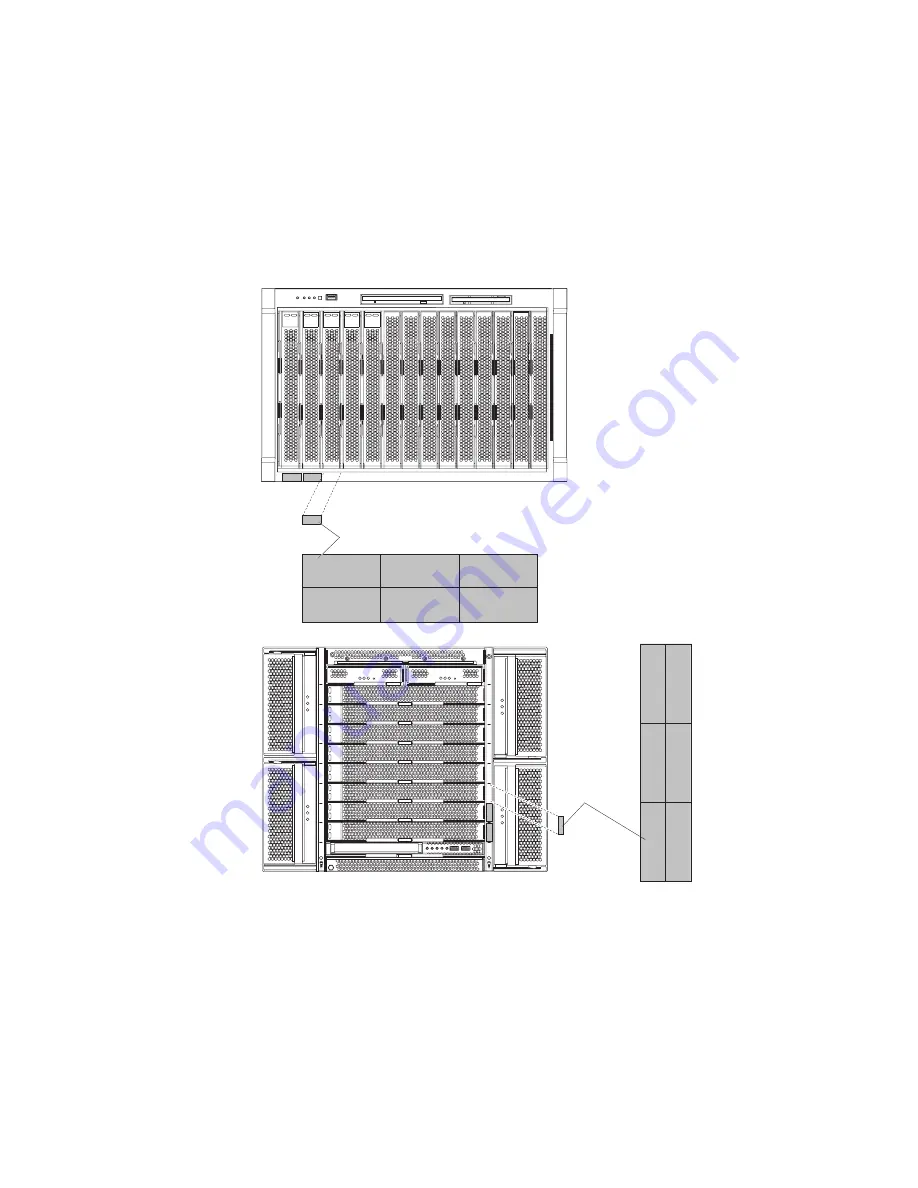
background image

A


set


of


user


labels


comes


with


the


BladeCenter


HS20


blade


server.


When


you


install


the


blade


server


in


the


BladeCenter


unit,


write


identifying


information


on


a


label


and


place


the


label


on


the


BladeCenter


unit


bezel.


The


following


illustrations


show


the


placement


of


the


labels,


adjacent


to


the


blade


servers,


on


two


typical


BladeCenter


unit


types.


Important:


Do


not


place


the


label


on


the


blade


server


itself


or


in


any


way


block


the


ventilation


holes


on


the


blade


server.


User label


User
label

CMM

1

CMM

2


Chapter


1.


Introduction


3

Summary of Contents for BladeCenter HS20 Type 8843

Page 1: ...Center unit complete the following procedures Install and configure the rack according to the documentation that came with the rack Install the BladeCenter unit into the rack and configure it according to the documentation provided with the BladeCenter unit Supply 200 240 V ac to the BladeCenter unit Install the latest firmware in all BladeCenter components Before you install the blade server into...

Page 2: ... connections and verify that all optional devices you installed are on the ServerProven list You can view the ServerProven list at http www ibm com pc compat Server working properly Problem solved Problem solved Hardware or software problem View support telephone numbers at http www ibm com planetwide View information about IBM support line at or view support telephone numbers at http www ibm com ...

Page 3: ...Eserver BladeCenter HS20 Type 8843 Installation and User s Guide ...

Page 4: ...ent of Limited Warranty Z125 4753 08 04 2004 on page 69 and Appendix C Notices on page 87 Second Edition January 2005 Copyright International Business Machines Corporation 2005 All rights reserved US Government Users Restricted Rights Use duplication or disclosure restricted by GSA ADP Schedule Contract with IBM Corp ...

Page 5: ...s 19 Removing the blade server from the BladeCenter unit 20 Opening the blade server cover 21 Removing the blade server bezel assembly 22 Installing a SCSI hard disk drive 23 Removing a SCSI hard disk drive 24 Installing memory modules 24 Installing an additional microprocessor 26 Installing an I O expansion card 29 Installing a small form factor expansion card 30 Installing a standard form factor...

Page 6: ... problems 60 Mouse problems 61 Network connection problems 61 Option problems 62 Power problems 62 Service processor BMC problems 63 Light path diagnostics 63 Diagnosing problems using light path diagnostics 63 Light path diagnostics LEDs 64 Appendix A Getting help and technical assistance 67 Before you call 67 Using the documentation 67 Getting help and information from the World Wide Web 68 Soft...

Page 7: ...Union EMC Directive conformance statement 91 Taiwanese Class A warning statement 91 Chinese Class A warning statement 92 Japanese Voluntary Control Council for Interference VCCI statement 92 Index 93 Contents v ...

Page 8: ...vi Eserver BladeCenter HS20 Type 8843 Installation and User s Guide ...

Page 9: ...alleert eerst de veiligheidsvoorschriften Ennen kuin asennat tämän tuotteen lue turvaohjeet kohdasta Safety Information Avant d installer ce produit lisez les consignes de sécurité Vor der Installation dieses Produkts die Sicherheitshinweise lesen Prima di installare questo prodotto leggere le Informazioni sulla Sicurezza Les sikkerhetsinformasjonen Safety Information før du installerer dette prod...

Page 10: ... of the caution or danger statement in the IBM Safety Information book For example if a caution statement begins with a number 1 translations for that caution statement appear in the IBM Safety Information book under statement 1 Be sure to read all caution and danger statements in this documentation before performing the instructions Read any additional safety information that comes with the serve...

Page 11: ...equipment when there is evidence of fire water or structural damage v Disconnect the attached power cords telecommunications systems networks and modems before you open the device covers unless instructed otherwise in the installation and configuration procedures v Connect and disconnect cables as described in the following table when installing moving or opening covers on this product or attached...

Page 12: ... drives fiber optic devices or transmitters are installed note the following v Do not remove the covers Removing the covers of the laser product could result in exposure to hazardous laser radiation There are no serviceable parts inside the device v Use of controls or adjustments or performance of procedures other than those specified herein might result in hazardous radiation exposure DANGER Some...

Page 13: ... power control button on the device and the power switch on the power supply do not turn off the electrical current supplied to the device The device also might have more than one power cord To remove all electrical current from the device ensure that all power cords are disconnected from the power source 1 2 Safety xi ...

Page 14: ...ement 13 DANGER Overloading a branch circuit is potentially a fire hazard and a shock hazard under certain conditions To avoid these hazards ensure that your system electrical requirements do not exceed branch circuit protection requirements Refer to the information that is provided with your device for electrical specifications Statement 21 CAUTION Hazardous energy is present when the blade is co...

Page 15: ...ort The blade server comes with a limited warranty For information about your warranty see Appendix B IBM Statement of Limited Warranty Z125 4753 08 04 2004 on page 69 You can obtain up to date information about the BladeCenter HS20 Type 8843 model at http www ibm com eserver xseries For more information about locating online documentation see Related documentation on page 4 Record information abo...

Page 16: ... has one of the bezels shown in the following illustration Note The illustrations in this document might differ slightly from the hardware Release levers Release button 2 Eserver BladeCenter HS20 Type 8843 Installation and User s Guide ...

Page 17: ...bel and place the label on the BladeCenter unit bezel The following illustrations show the placement of the labels adjacent to the blade servers on two typical BladeCenter unit types Important Do not place the label on the blade server itself or in any way block the ventilation holes on the blade server User label User label CMM 1 CMM 2 Chapter 1 Introduction 3 ...

Page 18: ...Depending on your BladeCenter product additional documents might be included on the Documentation CD In addition to the documentation in this library be sure to review the IBM BladeCenter Planning and Installation Guide for your BladeCenter unit type for information to help you prepare for system installation and configuration This document is available at http www ibm com pc eserver bladecenter T...

Page 19: ...ed in order of the most occurrences Click a document to view it and press Crtl F to use the Acrobat search function or Alt F to use the xpdf search function within the document Click Help for detailed information about using the Documentation Browser Notices and statements used in this document The caution and danger statements that appear in this document are also in the multilingual Safety Infor...

Page 20: ...emory v Failover Ethernet support v Hot swap drives on optional small computer system interface SCSI storage expansion unit v Light path diagnostics feature v Power on self test POST v Predictive Failure Analysis PFA alerts v Processor serial number access v Service processor that communicates with the management module to enable remote blade server management v SDRAM with serial presence detect S...

Page 21: ...provides full duplex FDX capability which enables simultaneous transmission and reception of data on the Ethernet local area network LAN The controllers support Wake on LAN technology v I O expansion The blade server comes with two connectors on the system board for an optional expansion card such as the Fibre Channel expansion card for adding more network communication capabilities to the blade s...

Page 22: ...d when the initial power is applied to the BladeCenter unit or when a blade server is inserted into the BladeCenter unit The possible settings for this policy are Redundant without performance impact Redundant with performance impact Non redundant You can configure and monitor the power environment by using the management module For more information about configuring and using power throttling see...

Page 23: ...0M video controller v LSI 1020 SCSI controller v Light path diagnostics v Local service processor BMC v RS 485 interface for communication with the management module v Automatic server restart ASR v Serial over LAN SOL v Intelligent Platform Management Interface IPMI v 4 USB buses for communication with keyboard mouse diskette drive and CD ROM drive Predictive Failure Analysis PFA alerts v Micropr...

Page 24: ...to see the components The following illustration shows the major components of a BladeCenter HS20 Type 8843 blade server Heat sink Microprocessor Microprocessor heat sink filler DIMM Bezel assembly Blade expansion unit connector SCSI hard disk drives 10 Eserver BladeCenter HS20 Type 8843 Installation and User s Guide ...

Page 25: ...turn on the blade server remotely by means of the service processor in the management module v If the operating system supports the Wake on LAN feature and the blade server power on LED is flashing slowly the Wake on LAN feature can turn on the blade server if the Wake on LAN feature has not been disabled through the management module Turning off the blade server When you turn off the blade server...

Page 26: ... can also press keyboard keys in the following sequence to switch keyboard mouse video control between blade servers NumLock NumLock blade_server_number Enter Where blade_server_number is the two digit number for the blade bay in which the blade server is installed Although the keyboard that is attached to the BladeCenter unit is a PS 2 style keyboard internal communication with it is through the ...

Page 27: ... LED When this green LED is lit it indicates that there is activity on the hard disk drive flash drive or network Location LED When this blue LED is lit it has been turned on by the system administrator to aid in visually locating the blade server The location LED on the BladeCenter unit will be lit also The location LED can be turned off through the management module Web interface or through IBM ...

Page 28: ...Microprocessor 1 and heatsink U66 Microprocessor socket 2 and heatsink U70 Blade expansion connector J132 I O expansion option connector J131 I O expansion option connector J34 Control panel connector Using system board switches The following illustration shows the location of switch block 2 SW2 Table 1 on page 15 describes the function of each switch on the switch block Switch block SW2 14 Eserve...

Page 29: ...rimary BIOS page On the BIOS starts from the backup BIOS page v 2 Wake On LAN bypass Off Enabled On Disabled default v 3 Reserved v 4 Reserved v 5 Reserved v 6 Clear CMOS Off Disabled On Enabled v 7 Reserved v 8 Bypass power on password during next server start Off Disabled default On Enabled Chapter 2 Power controls jumpers switches and indicators 15 ...

Page 30: ...rver is removed from the BladeCenter unit by pressing the light path diagnostics button The light path diagnostics power present LED CR111 is lit when the light path diagnostics button is pressed if power is available to relight the blade error LEDs If the light path diagnostics power present LED is not lit when the light path diagnostics button is pressed no power is available to light the blade ...

Page 31: ...rvice TEMP over temperature Check the BladeCenter blowers for correct operation and the air inlets for obstructions Make sure that the temperature of the room where the blade server is installed is within the limits specified by the Features and specifications on page 6 Light path diagnostics LED CR111 Lights to show that the light path diagnostics circuit is active and functioning Check the other...

Page 32: ...18 Eserver BladeCenter HS20 Type 8843 Installation and User s Guide ...

Page 33: ...r any additional procedures that you might have to perform before you remove or install the component v For a list of supported options for the blade server go to http www ibm com pc us compat System reliability guidelines To help ensure proper cooling and system reliability observe the following guidelines v Make sure that microprocessor socket 2 always contains either a microprocessor heat sink ...

Page 34: ...m the BladeCenter unit The following illustration shows how to remove the blade server from a typical BladeCenter unit Attention v To maintain proper system cooling do not operate the BladeCenter unit without a blade server expansion unit or filler blade installed in each blade bay v Note the bay number Reinstalling a blade server into a different bay than the one from which it was removed could h...

Page 35: ...nformation beginning on page vii and Installation guidelines on page 19 2 If the blade server is installed in a BladeCenter unit remove it see Removing the blade server from the BladeCenter unit on page 20 for instructions 3 Carefully lay the blade server down on a flat non conductive surface with the cover side up 4 Press the blade cover release on each side of the blade server and lift the cover...

Page 36: ... steps 1 Read the safety information beginning on page vii and Installation guidelines on page 19 2 Open the blade server cover see Opening the blade server cover on page 21 for instructions 3 Press the bezel assembly release and pull the bezel assembly away from the blade server approximately 1 2 cm 0 5 inch 4 Disconnect the control panel cable from the control panel connector 5 Pull the bezel as...

Page 37: ...dard form factor expansion card The standard form factor expansion card occupies the same area as the second hard disk drive To install a SCSI hard disk drive complete the following steps 1 Read the safety information beginning on page vii and Installation guidelines on page 19 2 Shut down the operating system turn off the blade server and remove the blade server from the BladeCenter unit See Remo...

Page 38: ...ade server can support a minimum of 256 MB and a maximum of 8 GB of system memory v The blade server comes with two DIMMs in the DIMM 1 J113 and DIMM 2 J111 memory connectors v When you install additional DIMMs be sure to install them as a pair in DIMM connectors 3 J112 and 4 J110 v Install the DIMMs in the following order Pair DIMM connectors First 1 J113 and 2 J111 Second 3 J112 and 4 J110 v Whe...

Page 39: ...o which you will install the DIMMs 7 Touch the static protective package that contains the DIMM option to any unpainted metal surface on the BladeCenter unit or any unpainted metal surface on any other grounded rack component in the rack you are installing the DIMM option in for at least 2 seconds then remove the DIMM from its package 8 To install the DIMMs repeat the following steps for each DIMM...

Page 40: ...consider when installing a microprocessor v Always install microprocessors that have the same cache size and type the same clock speed and identical internal and external clock frequencies including system bus speed v Make sure that the microprocessor with the lowest feature set is the startup bootstrap microprocessor which is installed in the microprocessor 1 socket U66 v For a list of microproce...

Page 41: ...8 Install the microprocessor a Remove the protective cover tape or label from the surface of the microprocessor socket if one is present b Touch the static protective package that contains the new microprocessor to any unpainted metal surface on the blade server or any unpainted metal surface on any other grounded rack component in the rack you are installing the microprocessor in for at least 2 s...

Page 42: ...press the microprocessor into the socket Microprocessor Microprocessor socket Alignment marks Attention v Do not use excessive force when pressing the microprocessor into the socket v Make sure that the microprocessor is oriented and aligned correctly in the socket before you try to close the lever e Carefully close the lever to secure the microprocessor in the socket 28 Eserver BladeCenter HS20 T...

Page 43: ...d by the BladeCenter unit in which the blade server is installed you can add an I O expansion card to the blade server I O expansion cards give the blade server additional connections for communicating on a network Your blade server supports installation of one I O expansion card of either the small form factor or standard form factor design You cannot install both sizes of I O expansion card in a...

Page 44: ... of compatible I O expansion cards on blade servers within the same BladeCenter unit The following sections describe how to install an I O expansion card in the blade server Installing a small form factor expansion card Install a small form factor expansion card near SCSI connector 1 J94 To install a small form factor expansion card complete the following steps 1 Read the safety information beginn...

Page 45: ...rd disk drive on page 24 You cannot have both a drive that is connected to SCSI connector 1 and a standard form factor expansion card installed in the blade server If you are removing the SCSI disk drive backup any information on it that you want to keep to another storage device If the SCSI hard disk drive that is installed in SCSI connector 1 is part of a RAID array delete the SCSI RAID array be...

Page 46: ...y P R E S S H E R E W H E N IN S TA LL IN G C A R D a Install the expansion card tray Secure the tray to the system board with the screws from the option kit or from the removed drive tray b Orient the expansion card and slide the notch in the narrow end of the card into the raised hook on the tray then gently pivot the wide end of the card into the expansion card connectors Note For device driver...

Page 47: ...65 7999 or 1 800 465 6666 within Canada Outside the U S and Canada call your IBM reseller or IBM marketing representative Note After you replace the battery you must reconfigure your blade server and reset the system date and time Statement 2 CAUTION When replacing the lithium battery use only IBM Part Number 33F8354 or an equivalent type battery recommended by the manufacturer If your system has ...

Page 48: ...ide the battery into place press the battery down into the socket 8 Close the blade server cover see Closing the blade server cover on page 36 Statement 21 CAUTION Hazardous energy is present when the blade server is connected to the power source Always replace the blade cover before installing the blade server 9 Reinsert the blade server into the bay in the BladeCenter unit 10 Turn on the blade s...

Page 49: ...lade server see Turning on the blade server on page 11 5 For certain options run the blade server Configuration Setup Utility program see Updating the blade server configuration on page 38 Note If you have just connected the power cords of the BladeCenter unit to electrical outlets you must wait until the power on LED on the blade server flashes slowly before pressing the power control button Inst...

Page 50: ...stallation guidelines on page 19 2 If you removed the blade bezel assembly replace it now see Installing the blade server bezel assembly on page 35 for instructions 3 Lower the cover so that the slots at the rear slide down onto the pins at the rear of the blade server as shown in the illustration Before closing the cover check that all components are installed and seated correctly and that you ha...

Page 51: ...jacent bays b When any blade server or option is in blade bay 7 through 14 in a BladeCenter unit or in blade bays 5 through 8 in a BladeCenter T unit power modules must be present in all four power module bays c To help ensure proper cooling performance and system reliability make sure that each of the blade bays on the front of the BladeCenter unit has a blade server expansion unit or filler blad...

Page 52: ... to bay number Reinstalling a blade server into a different blade bay from the one from which it was removed could have unintended consequences and you might have to reconfigure the blade server If this is the initial installation for the blade server in the BladeCenter unit you must configure the blade server through the Configuration Setup Utility program and install the blade server operating s...

Page 53: ...ette USB select button and the keyboard mouse video select button See Understanding the control panel and LEDs on page 12 for information about these buttons and their functions The Ethernet controllers on the blade server communicate with the network through the Ethernet compatible I O modules on the BladeCenter unit Network signals to and from the blade server or any expansion cards are automati...

Page 54: ...40 Eserver BladeCenter HS20 Type 8843 Installation and User s Guide ...

Page 55: ...am is part of the BIOS code in the blade server Use it to select the boot protocol and other boot options and to select a power management option For information about using this utility program see Using the PXE boot agent utility program on page 47 The IBM Remote Deployment Manager RDM Version 4 20 program is available for purchase You can use IBM RDM Version 4 20 or later to install a BIOS code...

Page 56: ...B devices installed in the blade server v System Information Select this choice to display information about the blade server When you make configuration changes through other options in the Configuration Setup Utility program some of those changes are reflected in the system information you cannot change settings directly in the system information Product Data Select this choice to view the machi...

Page 57: ...stored after three consecutive failures to find a boot record You can enable a virus detection test that checks for changes in the boot record when the blade server starts This choice is on the full Configuration Setup menu only v Advanced Setup Select this choice to change settings for advanced hardware features Important The blade server might malfunction if these options are incorrectly configu...

Page 58: ...t the time outs for the POST and OS loader watchdog timers and view BMC version information BMC Network Configuration Select this choice to set the network addresses of the BMC BMC System Event Log Select this choice to view and clear BMC event log entries v Save Settings Select this choice to save the changes you have made in the settings v Restore Settings Select this choice to cancel the change...

Page 59: ...ies operating system installations by providing updated device drivers and in some cases installing them automatically Note The ServerGuide program works only with 32 bit Windows operating systems If a later version of the ServerGuide program is available you can download a free image of the ServerGuide Setup and Installation CD or you can purchase the CD To download the image go to the IBM Server...

Page 60: ...CSI RAID configuration program to create logical drives Note Features and functions can vary slightly with different versions of the ServerGuide program When you start the ServerGuide Setup and Installation CD the program prompts you to complete the following tasks v Select your language v Select your keyboard layout and country v View the overview to learn about ServerGuide features v View the re...

Page 61: ...ng system Using the PXE boot agent utility program Use the Preboot Execution Environment PXE boot agent utility program to select the boot protocol and other boot options and to select a power management option Note The blade server does not support Remote Program Load RPL selection for the boot protocol option To start the PXE boot agent utility program complete the following steps 1 Turn on the ...

Page 62: ... firmware Download the latest firmware for the service processor from the IBM Support Web site at http www ibm com pc support Use the management module Web interface to update the service processor BMC firmware The Web interface is described in the IBM Eserver BladeCenter Management Module User s Guide Before installing the blade server in a BladeCenter unit go to http www ibm com pc support to do...

Page 63: ...http www ibm com pc support The Ethernet controllers in your blade server support failover which provides automatic redundancy for the Ethernet controllers Without failover you can have only one Ethernet controller from each server attached to each virtual LAN or subnet With failover you can configure more than one Ethernet controller from each server to attach to the same virtual LAN or subnet Ei...

Page 64: ...D level 1 mirror arrays in operating systems that are listed on the ServerProven list at http www ibm com pc compat For the blade server you must configure the SCSI RAID using the following programs v LSI Configuration Utility program v ServeRAID Manager program Using the LSI Logic Configuration Utility program You can use the LSI Logic Configuration Utility program to v Set the SCSI device scan o...

Page 65: ...ies and Mirroring Properties additional screens are displayed Using the ServeRAID configuration programs The IBM ServeRAID Support CD contains the ServeRAID Manager program which you can use to configure the hard disk drives for use with the LSI SCSI controller on the expansion unit For details about using these programs see the documentation that comes on the IBM ServeRAID Support CD Chapter 4 Co...

Page 66: ...52 Eserver BladeCenter HS20 Type 8843 Installation and User s Guide ...

Page 67: ...tte drive on a BladeCenter T unit The BladeCenter unit use USB for internal communication with these devices 2 Some operating systems such as Red Hat Linux 7 3 enable you to select the type of mouse that is being used If you are offered this choice select USB instead of PS 2 Although the mouse is a PS 2 style device communication with the mouse is through an internal USB bus in the BladeCenter uni...

Page 68: ...ee http www ibm com pc ww eserver xseries systems_management index html Downloading installation instructions To download operating system installation instructions complete the following steps 1 Go to the IBM Support Web page at http www ibm com pc support 2 From the Browse by product list select Servers 3 Under Select your product from the Family list select your server model then select Continu...

Page 69: ...n the IBM Documentation CD that comes with the BladeCenter unit for more information v ServerGuide problems The table in ServerGuide problems on page 58 lists problem symptoms and steps to correct the problems v Troubleshooting charts The Troubleshooting charts on page 59 list problem symptoms and steps to correct the problems v Diagnostic programs and error messages Real Time Diagnostics tests th...

Page 70: ...ccurred and the BIOS cannot initialize the monitor screen to display additional information Beep codes for specific problems Additional beep codes are listed in the following table Table 4 POST beep code descriptions Beep code Descriptions of the POST beep codes 1 1 4 BIOS ROM checksum in progress or failure Action 1 Move the BIOS code page jumper J12 to pins 2 and 3 to start from the backup BIOS ...

Page 71: ...uration error Start the Configuration Setup Utility program and make sure that the parallel port setting is correct 11xx Serial port error Make sure that the serial cable is connected correctly 1162 Serial port configuration conflict Start the Configuration Setup Utility program and make sure that the IRQ and I O port assignments that are needed by the serial port are available 1800 PCI adapter ha...

Page 72: ...ew all installed drives or the operating system cannot be installed v Make sure that there are no duplicate SCSI IDs or IRQ assignments v Make sure that the hard disk drive is connected correctly The operating system installation program continuously loops Make more space available on the hard disk The ServerGuide program will not start the operating system CD Make sure that the operating system C...

Page 73: ... replace the DIMM v If the DIMMs are not installed in pairs install the DIMMs starting with DIMM 1 and DIMM 2 Make sure that there is not an unpopulated DIMM slot in the middle or that DIMM 3 and DIMM 4 are installed before DIMM 1 and DIMM 2 v If the system halts make sure that the DIMMs installed in each pair are the same size speed type technology and physical design Swap DIMM 3 and DIMM 4 with ...

Page 74: ... of the Configuration Setup Utility program is enabled its default setting you must restart the blade server three times to force the system BIOS to reset the configuration settings to the default configuration the memory connector or bank of connectors enabled If the problem remains call for service Only the cursor appears Make sure that the keyboard video and mouse on the BladeCenter unit have n...

Page 75: ...ct USB If the problem remains call for service Network connection problems Symptom Suggested action One or more blade servers are unable to communicate with the network Make sure that v The I O modules for the network interface that you are using are installed in the correct bays and are configured and operating correctly See the Hardware Maintenance Manual and Troubleshooting Guide for your Blade...

Page 76: ...4 in the BladeCenter unit or blade bays 5 through 8 in the BladeCenter T unit power modules are in all four power bays d The power on LED on the blade server control panel is flashing slowly v If the power LED is flashing rapidly and continues to do so the blade server is not communicating with the management module reseat the blade server and go to step 3 v If the power LED is off either the blad...

Page 77: ...ocate the actual component that caused the error locate the lit error LED on that component The following steps illustrate how to use the light path diagnostics to diagnose a system error 1 Shut down the operating system turn off the blade server and remove the blade server from the BladeCenter unit see Turning off the blade server on page 11 and Removing the blade server from the BladeCenter unit...

Page 78: ...ower is available to relight the light path diagnostics LEDs for a small period of time after the blade server is removed from the BladeCenter unit During that period of time you can relight the light path diagnostics LEDs for a maximum of 25 seconds or less depending on the number of LEDs that are lit and the length of time the blade server is removed from the BladeCenter unit by pressing the lig...

Page 79: ...ce the microprocessor Temperature error TEMP The system temperature has exceeded a threshold level v Determine whether a blower on the BladeCenter unit has failed If it has replace the blower v Make sure that the room temperature is not too high see Features and specifications on page 6 for temperature information If the problem remains have the blade server serviced System board error SBRD The sy...

Page 80: ...66 Eserver BladeCenter HS20 Type 8843 Installation and User s Guide ...

Page 81: ...problems without outside assistance by following the troubleshooting procedures that IBM provides in the online help or in the publications that are provided with your system and software The information that comes with your system also describes the diagnostic tests that you can perform Most Eserver and IntelliStation systems operating systems and programs come with information that contains trou...

Page 82: ...pliances For information about which products are supported by Support Line in your country or region see http www ibm com services sl products For more information about Support Line and other IBM services see http www ibm com services or see http www ibm com planetwide for support telephone numbers In the U S and Canada call 1 800 IBM SERV 1 800 426 7378 Hardware service and support You can rece...

Page 83: ...he removal of parts and their return to IBM A part that replaces a removed part will assume the warranty service status of the removed part Unless IBM specifies otherwise these warranties apply only in the country or region in which you purchased the Machine THESE WARRANTIES ARE YOUR EXCLUSIVE WARRANTIES AND REPLACE ALL OTHER WARRANTIES OR CONDITIONS EXPRESS OR IMPLIED INCLUDING BUT NOT LIMITED TO...

Page 84: ...chine and other software updates from an IBM Internet Web site or from other electronic media and following the instructions that IBM provides If your problem can be resolved with a Customer Replaceable Unit CRU e g keyboard mouse speaker memory hard disk drive IBM will ship the CRU to you for you to install If the Machine does not function as warranted during the warranty period and your problem ...

Page 85: ...amage to your Machine only while it is 1 in IBM s possession or 2 in transit in those cases where IBM is responsible for the transportation charges Neither IBM nor your reseller are responsible for any of your confidential proprietary or personal information contained in a Machine which you return to IBM for any reason You should remove all such information from the Machine prior to its return Cir...

Page 86: ...CH VARY FROM STATE TO STATE OR JURISDICTION TO JURISDICTION Jurisdiction All of our rights duties and obligations are subject to the courts of the country in which you acquired the Machine Part 2 Country unique Terms AMERICAS ARGENTINA Jurisdiction The following is added after the first sentence Any litigation arising from this Statement of Limited Warranty will be settled exclusively by the Ordin...

Page 87: ...f Asuncion PERU Limitation of Liability The following is added at the end of this section In accordance with Article 1328 of the Peruvian Civil Code the limitations and exclusions specified in this section will not apply to damages caused by IBM s willful misconduct dolo or gross negligence culpa inexcusable URUGUAY Jurisdiction The following is added after the first sentence Any litigation arisin...

Page 88: ...to right to sell quiet possession or clear title or the goods are of a kind ordinarily acquired for personal domestic or household use or consumption then none of the limitations in this paragraph apply Governing Law The following replaces laws of the country in which you acquired the Machine in the first sentence laws of the State or Territory CAMBODIA AND LAOS Governing Law The following replace...

Page 89: ... the subject of the claim For purposes of this item the term Machine includes Machine Code and Licensed Internal Code LIC Arbitration The following is added under this heading Disputes arising out of or in connection with this Statement of Limited Warranty shall be finally settled by arbitration which shall be held in Bangalore India in accordance with the laws of India then in effect The arbitrat...

Page 90: ...ntence laws of the State of New York United States of America except when local law requires otherwise PHILIPPINES Limitation of Liability Item 3 in the fifth paragraph is replaced by the following SPECIAL INCLUDING NOMINAL AND EXEMPLARY DAMAGES MORAL INCIDENTAL OR INDIRECT DAMAGES FOR ANY ECONOMIC CONSEQUENTIAL DAMAGES OR Arbitration The following is added under this heading Disputes arising out ...

Page 91: ...untries provided the Machines have been announced and made available in such countries If you purchase a Machine in one of the Western European countries as defined above you may obtain warranty service for that Machine in any of those countries from either 1 an IBM reseller approved to perform warranty service or 2 from IBM provided the Machine has been announced and made available by IBM in the ...

Page 92: ...f Limited Warranty or related to its execution including summary proceedings will be submitted to the exclusive jurisdiction of the English courts 3 in Belgium and Luxembourg all disputes arising out of this Statement of Limited Warranty or related to its interpretation or its execution the law and the courts of the capital city of the country of your registered office and or commercial site locat...

Page 93: ...in the country of installation In Estonia Latvia and Lithuania all disputes arising in connection with this Statement of Limited Warranty will be finally settled in arbitration that will be held in Helsinki Finland in accordance with the arbitration laws of Finland then in effect Each party will appoint one arbitrator The arbitrators will then jointly appoint the chairman If arbitrators cannot agr...

Page 94: ...4 LOSS OF BUSINESS REVENUE GOODWILL OR ANTICIPATED SAVINGS FRANCE AND BELGIUM Limitation of Liability The following replaces the terms of this section in its entirety Except as otherwise provided by mandatory law 1 IBM s liability for any damages and losses that may arise as a consequence of the fulfillment of its obligations under or in connection with this Statement of Limited Warranty is limite...

Page 95: ...n of Liability The following paragraph is added to this section The limitations and exclusions specified in the Statement of Limited Warranty will not apply to damages caused by IBM with fraud or gross negligence and for express warranty The following sentence is added to the end of item 2 IBM s liability under this item is limited to the violation of essential contractual terms in cases of ordina...

Page 96: ...gence HUNGARY Limitation of Liability The following is added at the end of this section The limitation and exclusion specified herein shall not apply to liability for a breach of contract damaging life physical well being or health that has been caused intentionally by gross negligence or by a criminal act The parties accept the limitations of liability as valid provisions and state that the Secti...

Page 97: ...age to data 2 special indirect or consequential loss or 3 loss of profits business revenue goodwill or anticipated savings SLOVAKIA Limitation of Liability The following is added to the end of the last paragraph The limitations apply to the extent they are not prohibited under 373 386 of the Slovak Commercial Code SOUTH AFRICA NAMIBIA BOTSWANA LESOTHO AND SWAZILAND Limitation of Liability The foll...

Page 98: ...y of its suppliers or resellers liable for any of the following even if IBM or they were informed of the possibility of such losses 1 loss of or damage to data 2 special indirect or consequential loss or 3 loss of profits business revenue goodwill or anticipated savings Part 3 Warranty Information This Part 3 provides information regarding the warranty applicable to your Machine including the warr...

Page 99: ...of your receipt of the replacement 2 On site Service IBM or your reseller will either repair or exchange the failing Machine at your location and verify its operation You must provide suitable working area to allow disassembly and reassembly of the IBM Machine The area must be clean well lit and suitable for the purpose For some Machines certain repairs may require sending the Machine to an IBM se...

Page 100: ...below EU Country Telephone List Phone numbers are subject to change without notice For the warranty service contact telephone number in a country subsequently added to the EU and not yet reflected in the list below contact IBM in that country or visit the website above for a current telephone listing Austria 43 1 24592 5901 Latvia 386 61 1796 699 Belgium 32 70 23 3392 Lithuania 386 61 1796 699 Cyp...

Page 101: ...NTY OF ANY KIND EITHER EXPRESS OR IMPLIED INCLUDING BUT NOT LIMITED TO THE IMPLIED WARRANTIES OF NON INFRINGEMENT MERCHANTABILITY OR FITNESS FOR A PARTICULAR PURPOSE Some states do not allow disclaimer of express or implied warranties in certain transactions therefore this statement may not apply to you This information could include technical inaccuracies or typographical errors Changes are perio...

Page 102: ...in the United States other countries or both UNIX is a registered trademark of The Open Group in the United States and other countries Java and all Java based trademarks and logos are trademarks of Sun Microsystems Inc in the United States other countries or both Adaptec and HostRAID are trademarks of Adaptec Inc in the United States other countries or both Linux is a trademark of Linus Torvalds i...

Page 103: ...ailable and may not include user manuals or all program functionality Product recycling and disposal This unit contains materials such as circuit boards cables electromagnetic compatibility gaskets and connectors which may contain lead and copper beryllium alloys that require special handling and disposal at end of life Before this unit is disposed of these materials must be removed and recycled o...

Page 104: ...manual may cause harmful interference to radio communications Operation of this equipment in a residential area is likely to cause harmful interference in which case the user will be required to correct the interference at his own expense Properly shielded and grounded cables and connectors must be used in order to meet FCC emission limits IBM is not responsible for any radio or television interfe...

Page 105: ... EEC on the approximation of the laws of the Member States relating to electromagnetic compatibility IBM cannot accept responsibility for any failure to satisfy the protection requirements resulting from a nonrecommended modification of the product including the fitting of non IBM option cards This product has been tested and found to comply with the limits for Class A Information Technology Equip...

Page 106: ...Chinese Class A warning statement Japanese Voluntary Control Council for Interference VCCI statement 92 Eserver BladeCenter HS20 Type 8843 Installation and User s Guide ...

Page 107: ... SCSI 14 SCSI expansion 14 system board 14 controller enable or disable Ethernet 42 enable or disable SCSI 42 Ethernet 49 memory 7 controller enumeration 49 cover closing 36 opening 21 D daughter card I O expansion card 30 description DIMM error LED 16 microprocessor error LED 16 SW2 system board switch 15 SW4 system board error LEDs 16 diagnostic tools 55 DIMM error LED description 16 DIMM See me...

Page 108: ...tling 8 LSI logic configuration utility program description 41 M major components 10 memory configuration changes 24 memory continued hot spare 43 problems 59 specifications 9 memory module installing 24 order of installation 24 specifications 7 9 supported 9 24 microprocessor heat sink 29 installing 26 problem 59 specifications 9 microprocessor error LED description 16 N NOS installation with Ser...

Page 109: ...on card installing 30 specifications BladeCenter HS20 in a non NEBS ETSI environment 9 standard form factor expansion card installing 31 start options 43 starting the blade server 11 startup sequence setting 43 static electricity 19 static sensitive devices handling 19 stopping the blade server 11 SW2 system board switch description 15 SW4 location light path diagnostics 16 switch power on passwor...

Page 110: ...96 Eserver BladeCenter HS20 Type 8843 Installation and User s Guide ...

Page 111: ......

Page 112: ... Part Number 59P4365 Printed in USA 1P P N 59P4365 ...

Reviews: