background image

Notes:

1.

Copper pass-thru module cable connectors are marked as A, B, C, D, and E
to indicate their channel number.

2.

The port-3 E connector is not used.

Information LEDs

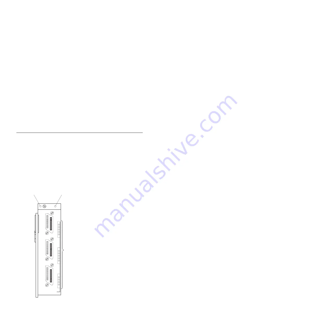
There are two sets of LEDs on the copper pass-thru module front panel. The
first row of LEDs at the top of the I/O module represent I/O-module status
and include the power LED and the copper pass-thru module error LED (!).
The second set of LEDs are grouped in an LED matrix that indicates the link
status for each copper-port channel and copper-port errors. The following
illustration shows the LEDs on the copper pass-thru module. A description of
each LED follows the illustration.

1

5

6

10

11

14

1

2

3

LINK OK

!

Copper Pass-thru
Module error LED

Power LED

Link OK LEDs

Figure 6. Information LEDs

Chapter 3. Information LEDs and external ports

25

Summary of Contents for BladeCenter Copper Pass-thru

Page 1: ...IBM BladeCenter Copper Pass thru Module Installation Guide...

Page 2: ......

Page 3: ...IBM BladeCenter Copper Pass thru Module Installation Guide...

Page 4: ...the product Read the IBM Safety Information and the License Agreement for Machine Code LAMC document on the IBM Documentation CD Read the Environmental Notices and User Guide on the IBM Environmental...

Page 5: ...ru module 14 Removing a copper pass thru module 20 Chapter 3 Information LEDs and external ports 23 Front panel 23 Information LEDs 25 Chapter 4 Completing the installation 27 Cable connection 27 Conn...

Page 6: ...ralia and New Zealand Class A statement 37 United Kingdom telecommunications safety requirement 37 European Union EMC Directive conformance statement 37 Taiwanese Class A warning statement 38 Chinese...

Page 7: ...rt eerst de veiligheidsvoorschriften Ennen kuin asennat t m n tuotteen lue turvaohjeet kohdasta Safety Information Avant d installer ce produit lisez les consignes de s curit Vor der Installation dies...

Page 8: ...statement with translated versions of the caution or danger statement in the IBM Safety Information book For example if a caution statement begins with a number 1 translations for that caution statem...

Page 9: ...quipment when there is evidence of fire water or structural damage v Disconnect the attached power cords telecommunications systems networks and modems before you open the device covers unles instruct...

Page 10: ...m battery replace it only with the same module type made by the same manufacturer The battery contains lithium and can explode if not properly used handled or disposed of Do not v Throw or immerse int...

Page 11: ...he device v Use of controls or adjustments or performance of procedures other than those specified herein might result in hazardous radiation exposure DANGER Some laser products contain an embedded Cl...

Page 12: ...e Statement 8 CAUTION Never remove the cover on a power supply or any part that has the following label attached Hazardous voltage current and energy levels are present inside any component that has t...

Page 13: ...associated with accessories sold with this product will expose you to lead a chemical known to the State of California to cause cancer and birth defects or other reproductive harm Wash hands after ha...

Page 14: ...xii IBM BladeCenter Copper Pass thru Module Installation Guide...

Page 15: ...onnection that enables the blade servers in the BladeCenter unit to connect to an existing network infrastructure No configuration of the copper pass thru module is required Notes 1 In this document t...

Page 16: ...nstallation Guide the following related documentation is provided with your BladeCenter unit and blade server v Rack Installation Instructions This document contains the instructions to install your B...

Page 17: ...ce technicians Depending on your blade server model additional documents might be included on the IBM BladeCenter unit Documentation CD Features and specifications This section provides a summary of t...

Page 18: ...es and statements are used in this book v Note These notices provide important tips guidance or advice v Important These notices provide information or advice that might help you avoid inconvenient or...

Page 19: ...lightly from your hardware 1 5 6 10 11 14 2 3 LIN K OK 1 Serial number label Information LEDs Copper Pass thru Module Copper ports 3 Release latch For more information about the components of the fron...

Page 20: ...hru module cable One copper pass thru module cable comes with the copper pass thru module Copper pass thru module cables and other optional components for the copper pass thru module are listed at htt...

Page 21: ...ule bay 4 I O module bay 2 Attention To maintain proper system cooling and performance each module bay must contain either a module or a filler module each blade bay must contain either a blade server...

Page 22: ...twork connection for the second Ethernet controller in each blade server install an I O module in I O module bay 2 In BladeCenter units that support four I O modules if you install an I O expansion ca...

Page 23: ...unit must both be of the same type and must both support the I O expansion card network interface type For example if you add an Ethernet expansion card to a blade server the modules in I O module ba...

Page 24: ...for the controller 4 Ping an external computer on the network connected to the I O module If you can ping the external computer the Ethernet controller that you enabled is associated with the I O mod...

Page 25: ...BladeCenter unit go to http www 03 ibm com services supline products System reliability considerations Attention To help ensure proper cooling performance and system reliability make sure that v Each...

Page 26: ...because heating reduces indoor humidity and increases static electricity v On a BladeCenter T unit use an ESD wrist strap and the ESD connectors Electrostatic discharge ESD is the release of stored s...

Page 27: ...Location of ESD connector rear of unit ESD connector TOP D TOP D BTM E BTM E 2 4 1 3 CRT MJR MNR 2 Alarms 1 Chapter 2 Installing and removing a copper pass thru module 13...

Page 28: ...ce v Use of controls or adjustments or performance of procedures other than those specified herein might result in hazardous radiation exposure DANGER Some laser products contain an embedded Class 3A...

Page 29: ...ched Hazardous voltage current and energy levels are present inside any component that has this label attached There are no serviceable parts inside these components If you suspect a problem with one...

Page 30: ...install a copper pass thru module in an I O module bay in the rear of an IBM Eserver BladeCenter Type 8677 or similar BladeCenter unit 1 5 6 10 11 14 2 3 LI N K O K 1 I O module 16 IBM BladeCenter Cop...

Page 31: ...odule 1 Make sure that you are using the latest versions of device drivers firmware and BIOS code for your blade server and management module Go to the IBM Support Web site http www ibm com pc support...

Page 32: ...contains the copper pass thru module to any unpainted metal surface of the BladeCenter unit chassis or any unpainted metal surface on any other grounded rack component for at least two seconds 7 Remov...

Page 33: ...tep 13 13 Attach any cables required by the copper pass thru module See Chapter 4 Completing the installation on page 27 for instructions For the location of the connectors on the BladeCenter unit see...

Page 34: ...hese components If you suspect a problem with one of these parts contact a service technician Complete the following steps to remove a copper pass thru module 1 If the BladeCenter unit is an IBM Eserv...

Page 35: ...ler module Filler module 2 3 LINK OK LINK OK 1 4 Slide the module out of the bay and set it aside 5 Place either another I O module or a filler module in the bay within 1 minute 6 If you placed anothe...

Page 36: ...22 IBM BladeCenter Copper Pass thru Module Installation Guide...

Page 37: ...s shown in the following illustration Each interface port supports up to five channels of bi directional communication which support fourteen external communication channels Note The port 3 E connecto...

Page 38: ...Port 1 transceiver 1 A 2 Port 1 transceiver 2 B 3 Port 1 transceiver 3 C 4 Port 1 transceiver 4 D 5 Port 1 transceiver 5 E 6 Port 2 transceiver 6 A 7 Port 2 transceiver 7 B 8 Port 2 transceiver 8 C 9...

Page 39: ...odule status and include the power LED and the copper pass thru module error LED The second set of LEDs are grouped in an LED matrix that indicates the link status for each copper port channel and cop...

Page 40: ...his LED indicates that the I O module has an error If the I O module fails the POST this error LED is lit LINK OK LEDs There are fourteen green LINK OK LEDs on the right side of the LED matrix on the...

Page 41: ...g network infrastructure for configuration information Cable connection The copper pass thru module is connected to existing network infrastructure using copper CAT5E cables One cable comes with the c...

Page 42: ...en insert the cable connector in the port connector Make sure that the cable is routed upwards in the rack cabinet this cable route provides for the 45 upwards angle of the cable connector 2 Press on...

Page 43: ...nter unit on the IBM BladeCenter unit Documentation CD Make sure that you are using the latest versions of device drivers firmware and BIOS code for your blade server and management module If these it...

Page 44: ...r unit Management Module User s Guide on the IBM BladeCenter unit or option Documentation CD for general information on managing BladeCenter I O modules If you still have a system configuration proble...

Page 45: ...Go to the IBM support Web site at http www 947 ibm com support entry portal docdisplay brand 5000008 lndocid SERV CALL to check for technical information hints tips and new device drivers or to submit...

Page 46: ...ervice and support Through IBM Support Line you can get telephone assistance for a fee with usage configuration and software problems with xSeries servers BladeCenter products IntelliStation workstati...

Page 47: ...Y 10504 1785 U S A INTERNATIONAL BUSINESS MACHINES CORPORATION PROVIDES THIS PUBLICATION AS IS WITHOUT WARRANTY OF ANY KIND EITHER EXPRESS OR IMPLIED INCLUDING BUT NOT LIMITED TO THE IMPLIED WARRANTIE...

Page 48: ...BladeCenter ServerProven C2T Interconnect TechConnect Chipkill ThinkPad EtherJet Tivoli e business logo Tivoli Enterprise Eserver Update Connector FlashCopy Wake on LAN IBM XA 32 IBM logo XA 64 Intel...

Page 49: ...00 bytes MB stands for approximately 1 000 000 bytes and GB stands for approximately 1 000 000 000 bytes When referring to hard disk drive capacity or communications volume MB stands for 1 000 000 byt...

Page 50: ...battery information The battery must be recycled or disposed of properly Recycling facilities may not be available in your area For information on disposal of batteries outside the United States go to...

Page 51: ...not cause harmful interference and 2 this device must accept any interference received including interference that may cause undesired operation Industry Canada Class A emission compliance statement T...

Page 52: ...lass A equipment were derived for commercial and industrial environments to provide reasonable protection against interference with licensed communication equipment Attention This is a Class A product...

Page 53: ...C Class A notice 36 features 3 firmware upgrade 29 front panel 23 G general requirements 3 H handling static sensitive devices 11 hardware problems 29 I I O module LEDs 25 I O module fault LED 26 iden...

Page 54: ...static sensitive devices handling 11 status and failure LEDs 3 supported options Web site 11 system reliability 11 T technical specifications 3 trademarks 34 transmission rates 3 troubleshooting hardw...

Page 55: ......

Page 56: ...Part Number 25R4622 02 Printed in USA...

Reviews: