background image

Rear view

1

2

3

4

5

6

7

8

Index

Description

CRU part

number

(Tier 1)

CRU part

number

(Tier 2)

FRU part

number

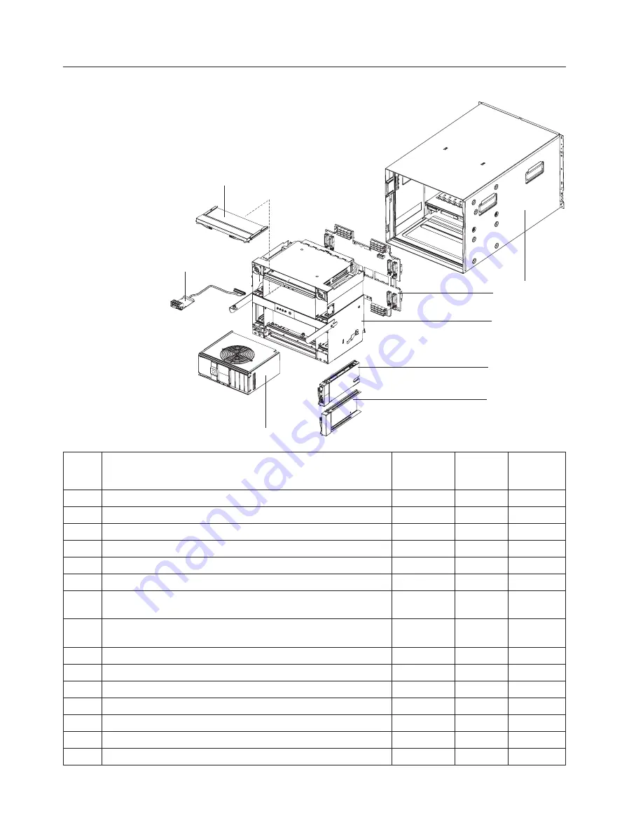
1

Chassis shell (without shuttle)

31R3308

2

Midplane (older models, chassis hardware version v6 or earlier)

1

25R5780

2

Midplane (newer models, chassis hardware version v8 or later)

1

44X2302

3

Shuttle, with card and cable assembly (all models)

31R3331

4

Management module (all models)

60Y0621

5

Filler, I/O module bays 1-6 and management module (all models)

25R9934

6

Blower module (older models, chassis hardware version v6 or
earlier)

2

44E5083

6

Enhanced blower module (newer models, chassis hardware
version v8 or later)

2

68Y8205

7

Card and cable assembly, rear LED/serial connector (all models)

31R3307

8

Filler, I/O module bays 7-10, double high (all models)

31R3311

Cable, serial port breakout

40K9608

Cable, serial USB (option)

43X0510

Cable, switch stack, 1 meter (option)

44R8302

Card, 4x Expansion

49Y9976

Cisco Nexus 4001i switch module

46M6072

26

BladeCenter H Type 8852, 7989, and 1886: Problem Determination and Service Guide

Summary of Contents for 8852 - BladeCenter H Rack-mountable

Page 1: ...BladeCenter H Type 8852 7989 and 1886 Problem Determination and Service Guide...

Page 2: ......

Page 3: ...BladeCenter H Type 8852 7989 and 1886 Problem Determination and Service Guide...

Page 4: ...ranty Information document and the IBM Safety Information and IBM Systems and Environmental Notices and User Guide documents on the IBM Documentation CD Seventh Edition September 2010 Copyright IBM Co...

Page 5: ...placing a fan pack 39 Removing a blade server 41 Installing a blade server 42 Removing an I O module 44 Installing an I O module 45 Removing a management module 46 Installing a management module 47 Re...

Page 6: ...erence EMI Class A statement 69 People s Republic of China Class A electronic emission statement 69 Taiwan Class A compliance statement 69 Index 71 iv BladeCenter H Type 8852 7989 and 1886 Problem Det...

Page 7: ...n tuotteen lue turvaohjeet kohdasta Safety Information Avant d installer ce produit lisez les consignes de s curit Vor der Installation dieses Produkts die Sicherheitshinweise lesen Prima di installar...

Page 8: ...2 Make sure that the exterior cover is not damaged loose or broken and observe any sharp edges 3 Check the power cords v Make sure that the third wire ground connector is in good condition Use a meter...

Page 9: ...is available to turn off the power if necessary When you are working with powered on electrical equipment use only one hand Keep the other hand in your pocket or behind your back to avoid creating a c...

Page 10: ...ter or structural damage v Disconnect the attached power cords telecommunications systems networks and modems before you open the device covers unless instructed otherwise in the installation and conf...

Page 11: ...products such as CD ROMs DVD drives fiber optic devices or transmitters are installed note the following v Do not remove the covers Removing the covers of the laser product could result in exposure to...

Page 12: ...d the power switch on the power supply do not turn off the electrical current supplied to the device The device also might have more than one power cord To remove all electrical current from the devic...

Page 13: ...ect a problem with one of these parts contact a service technician Statement 12 CAUTION The following label indicates a hot surface nearby Statement 13 DANGER Overloading a branch circuit is potential...

Page 14: ...y is present when the blade is connected to the power source Always replace the blade cover before installing the blade United Kingdom Notice to Customers This apparatus is approved under approval num...

Page 15: ...v BladeCenter H Installation and User s Guide This printed document contains instructions for setting up the BladeCenter unit and general information about the BladeCenter unit including information a...

Page 16: ...figure BladeCenter components for Serial over LAN SOL operation The SOL connection provides access to the text console command prompt on each blade server and enables the blade servers to be managed f...

Page 17: ...t help you avoid inconvenient or problem situations v Attention These notices indicate potential damage to programs devices or data An attention notice is placed just before the instruction or situati...

Page 18: ...kg 90 lbs Environment v Air temperature BladeCenter unit on Altitude 0 to 914 m 3000 ft 10 to 35 C 50 to 95 F Altitude 914 m to 2134 m 3000 ft to 7000 ft 10 to 32 C 50 to 90 F BladeCenter unit off 40...

Page 19: ...illustration shows the LEDs on each power module Fan error LED Power module error LED AC power LED DC power LED The LEDs on each power module indicate the condition of the power module and fan pack Fo...

Page 20: ...all power modules Location When this blue LED is lit or flashing it has been turned on by the system administrator to aid in visually locating the BladeCenter unit If a blade server requires attention...

Page 21: ...This panel contains indicators and controls for the blade server See the documentation that comes with your blade server for information about the blade server control panel Rear view This section ide...

Page 22: ...ector This connector provides direct access to the serial ports on each of the 14 blade server bays Use this connector to attach the optional serial port breakout cable and connect up to 14 local cons...

Page 23: ...ete the following steps 1 Shut down the operating systems and turn off any blade servers See the documentation that comes with the blade server for detailed instructions Statement 5 CAUTION The power...

Page 24: ...10 BladeCenter H Type 8852 7989 and 1886 Problem Determination and Service Guide...

Page 25: ...See Troubleshooting tables on page 12 for more information v Light path diagnostic LEDs Use the light path diagnostic LEDs on the BladeCenter unit and the BladeCenter components to identify system er...

Page 26: ...step is preceded by Trained service technician only that step must be performed only by a trained service technician Symptom Action A blade server power on LED flashes rapidly for an extended amount...

Page 27: ...mptom Action A fan pack is running at full speed 1 Make sure that at least one management module is installed and it is active and working 2 Reseat the following components a Power module b Fan pack 1...

Page 28: ...ke sure that v The device cables are connected to the active management module not the USB ports on the media tray v The KVM is owned by a blade server that supports KVM Management module problems v F...

Page 29: ...ment module v The network cable is not connected to the serial port on the active redundant management module v The IP address or host name is correct 2 Reseat the management module 3 Reset and reconf...

Page 30: ...owns the KVM is turned on v The KVM is owned by a blade server that supports KVM 2 Reseat the monitor cable 3 Replace the monitor Power problems v Follow the suggested actions in the order in which th...

Page 31: ...the instructions for those LEDs in this section Over temperature The system temperature has exceeded a threshold level 1 Determine whether a blower module has failed If it has replace the blower modu...

Page 32: ...agement Module Installation Guide for more information 3 Replace the management module Power module AC power LED is lit DC power LED not lit A system fault has shut down the power module or the power...

Page 33: ...d by timestamp with the most recent entry first You can sort the entries by severity source or timestamp by clicking on the appropriate column heading v You can filter the entries to show only the ent...

Page 34: ...3 Disengage power modules 2 3 and 4 one at a time To do this pull the release handle to the open position and slide the power module out of its bay approximately 1 inch 4 Disengage the I O modules one...

Page 35: ...r has this failure been reported before v Diagnostic program type and version level v Hardware configuration print the screen with the system summary information v BIOS code level v Operating system t...

Page 36: ...22 BladeCenter H Type 8852 7989 and 1886 Problem Determination and Service Guide...

Page 37: ...lls a Tier 1 CRU at your request you will be charged for the installation v Tier 2 customer replaceable unit You may install a Tier 2 CRU yourself or request IBM to install it at no additional charge...

Page 38: ...with fan pack 39Y7415 5 Filler power module all models 31R3304 6 Fan pack models equipped with 2900W power module only 43V7099 7 CD RW drive primary model 4Xx 39M3545 7 CD RW drive alternate model 4Xx...

Page 39: ...43X0457 9 System service cards model 4Xx 25R5676 10 Filler blade server all models except 4Sx 39M3317 Filler optical drive 49Y4868 Filler optical drive model 4Sx 46C5496 1 Your BladeCenter is equippe...

Page 40: ...le bays 1 6 and management module all models 25R9934 6 Blower module older models chassis hardware version v6 or earlier 2 44E5083 6 Enhanced blower module newer models chassis hardware version v8 or...

Page 41: ...switch option 44W4411 Module Qlogic 4 GB fibre channel 10 port full fabric switch option 46C7009 Module Qlogic 4 GB fibre channel 20 port full fabric switch option 46C7010 Module Qlogic 4 GB 850 nm fi...

Page 42: ...Japan Mexico United States of America 26R0009 Cable 30A 1 phase Korea 39M5436 Cable IEC 309 32A IEC 320 C20 Worldwide except Australia Canada Japan Korea Mexico New Zealand United States of America 3...

Page 43: ...om power to install or replace any of the hot swap modules in the BladeCenter unit You must to shut down the operating system and turn off a hot swap blade server before you remove the blade server bu...

Page 44: ...nit and other electronic devices To avoid damage keep static sensitive devices in their static protective packages until you are ready to install them To reduce the possibility of electrostatic discha...

Page 45: ...m your hardware Removing a bezel When working with some devices such as the media tray and power modules you must first remove the top or bottom bezels to access the devices To remove either bezel com...

Page 46: ...ttons Release buttons 1 Align the blue tabs on the ends of the bezel with the corresponding holes in the front of the BladeCenter unit 2 Firmly press the bezel into the BladeCenter unit until the tabs...

Page 47: ...compatible only with chassis hardware version v6 midplane FRU 25R5780 or earlier v Media module FRU PN 31R3305 v Media module FRU PN 43X0299 v Media module FRU PN 44X2268 Removing the media tray and...

Page 48: ...r clip Note These instructions assume that the BladeCenter unit is connected to power 1 Make sure that the media tray is on a clean static free surface with the circuit board facing up Attention To pr...

Page 49: ...nd 4 provide power for domain B blade slots 8 to 14 The following is an example of a supported configuration v Domain A Power Module 1 2900W Power Module 2 2900W v Domain B Power Module 3 2980W Power...

Page 50: ...ions for shutting down the blade server operating system and turning off the blade server Statement 8 CAUTION Never remove the cover on a power supply or any part that has the following label attached...

Page 51: ...you are replacing a 2900W power module with a new one remove the fan pack for installation on the new 2900W power module see Removing and replacing a fan pack on page 39 Note Do not attempt to remove...

Page 52: ...module bays the rear connector on the power module must be facing down v For the lower power module bays the rear connector on the power module must be facing up 4 Slide the module into the bay until...

Page 53: ...cedures Removing a fan pack To remove a fan pack from a 2900W power module complete the following steps Handle Release tabs 1 Remove the selected power module see Removing a power module on page 36 2...

Page 54: ...rallel with the bottom of the module with the power module rear connector facing up 2 Slide the fan pack into position on the power module until it stops and locks into place 3 Rotate the power module...

Page 55: ...rmation that begins on page v and Installation guidelines on page 29 2 Shut down the blade server operating system then shut down the blade server See the documentation that comes with your blade serv...

Page 56: ...l a blade server complete the following steps Release handles open Note These instructions assume that the BladeCenter unit is connected to power 1 Select the bay for the blade server Notes a Dependin...

Page 57: ...e identifying information on one of the labels that come with the blade server then place the label on the BladeCenter unit top bezel just above the blade server Important Do not place the label on th...

Page 58: ...ull the release handle or handles to the open position The module moves out of the bay approximately 0 6 cm 0 25 inch Note The modules and fillers in I O bays 1 through 6 each have one release handle...

Page 59: ...e the following steps I O module Module filler I O module Single module filler Double module filler Release handles open Release handle open Note These instructions assume that the BladeCenter unit is...

Page 60: ...mary management module for up to 45 minutes the second redundant management module needs the time to receive initial status information and firmware levels from the primary management module Managemen...

Page 61: ...he release handle to the closed position 4 Reconnect all cables to the module 5 If this is the only management module in the BladeCenter unit restore the configuration from the configuration file that...

Page 62: ...tion in relation to the equipment Compliance with such government regulations also depends on a variety of additional factors including the duration of employees exposure and whether employees wear he...

Page 63: ...1 Make sure that the handle on the blower module is in the open position 2 Orient the blower module to the selected blower module bay v For the upper bay the handle must be on the right v For the low...

Page 64: ...idelines on page 29 2 Shut down the operating systems and turn off any blade servers in the BladeCenter unit See the documentation that comes with the blade server for detailed instructions 3 Disconne...

Page 65: ...er on page 33 Make sure each component is pulled out of the BladeCenter unit about 2 54 cm 1 inch Note You do not have to remove any of these components completely from the BladeCenter unit 10 Loosen...

Page 66: ...ll move back fully into the BladeCenter chassis 5 Tighten the captive thumbscrews on the release handles 6 Install the upper and lower shipping brackets on the rear of the BladeCenter unit and the rac...

Page 67: ...unit until the release tabs lock it into place see Installing the media tray and optical drive or optical drive filler on page 34 10 Install the top and bottom bezels see Installing a bezel on page 3...

Page 68: ...on its top on a sturdy surface 5 Disconnect the assembly cable from the midplane connector Note the routing of the cable for use during reinstallation 6 Remove the two studs that attach the serial co...

Page 69: ...t see Installing the shuttle on page 52 6 Reconnect the power to the BladeCenter unit see Supplying power to the BladeCenter unit on page 9 7 Restart any blade servers that were shut down in the Blade...

Page 70: ...blade server for detailed instructions 3 Disconnect the power from the BladeCenter unit see Disconnecting power from the BladeCenter unit on page 9 4 Remove the shuttle from the BladeCenter unit see R...

Page 71: ...ure that the lower ac cable bracket is pulled away from the shuttle Attention Make sure that the midplane is properly positioned between the locating tabs to prevent damage to the midplane 2 Place the...

Page 72: ...the BladeCenter unit see Supplying power to the BladeCenter unit on page 9 10 Restart any blade servers that were shut down in the BladeCenter unit See the documentation that comes with the blade ser...

Page 73: ...configured with the same static IP address You can use the management module to assign a new static IP address To establish connectivity the management module attempts to use Dynamic Host Control Prot...

Page 74: ...rver and operating system for instructions BladeCenter networking guidelines Make sure that the network infrastructure is configured before you connect the BladeCenter unit to network Each blade serve...

Page 75: ...by following the troubleshooting procedures that IBM provides in the online help or in the documentation that is provided with your IBM product The documentation that comes with IBM systems also desc...

Page 76: ...on see http www ibm com services sl products For more information about Support Line and other IBM services see http www ibm com services or see http www ibm com planetwide for support telephone numbe...

Page 77: ...BILITY OR FITNESS FOR A PARTICULAR PURPOSE Some states do not allow disclaimer of express or implied warranties in certain transactions therefore this statement may not apply to you This information c...

Page 78: ...arks of others Important notes Processor speed indicates the internal clock speed of the microprocessor other factors also affect application performance CD or DVD drive speed is the variable read rat...

Page 79: ...ntation of appropriate remedial measures to mitigate such environmental contamination Implementation of such remedial measures is a customer responsibility Table 1 Limits for particulates and gases Co...

Page 80: ...s and connectors must be used in order to meet FCC emission limits IBM is not responsible for any radio or television interference caused by using other than recommended cables and connectors or by un...

Page 81: ...rzustellen sind die Ger te wie in den Handb chern beschrieben zu installieren und zu betreiben Des Weiteren d rfen auch nur von der IBM empfohlene Kabel angeschlossen werden IBM bernimmt keine Verantw...

Page 82: ...Voluntary Control Council for Interference VCCI If this equipment is used in a domestic environment radio interference may occur in which case the user may be required to take corrective actions Japan...

Page 83: ...Russia Electromagnetic Interference EMI Class A statement People s Republic of China Class A electronic emission statement Taiwan Class A compliance statement Appendix B Notices 69...

Page 84: ...70 BladeCenter H Type 8852 7989 and 1886 Problem Determination and Service Guide...

Page 85: ...ront system panel LEDs 6 G gaseous contamination 65 getting help 61 H hardware problems 11 hardware service and support 62 heat output 4 help getting 61 I I O module configuring 59 installing 45 probl...

Page 86: ...module 44 management module 46 midplane 56 power module 36 rear LED serial connector assembly 54 shuttle 50 removing and replacing media tray 33 Optical drive 33 Optical drive filler 33 Removing and...

Page 87: ......

Page 88: ...Part Number 81Y1107 Printed in USA 1P P N 81Y1107...

Reviews: