background image

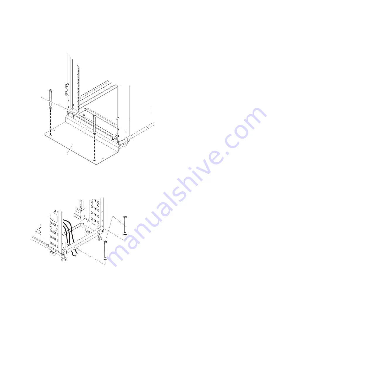
Bolt the rear of the rack to the floor surface through the holes in the lower frame by using two
bolts and washers.

v

If a front stabilizer bracket or stabilizer plate is not installed

, bolt the front of the rack to the

floor surface through the holes in the lower frame by using two bolts and washers.

Stabilizer bracket

Bolts

Figure 10. Bolting the front stabilizer to the floor surface

Bolts

Rack rear

Figure 11. Bolting the rear of the rack to the floor surface

Installing the 7953-94X and 7965-94Y rack and features

11

Summary of Contents for 7953-94X

Page 1: ...Power Systems Installing the 7953 94X and 7965 94Y rack and features ...

Page 2: ......

Page 3: ...Power Systems Installing the 7953 94X and 7965 94Y rack and features ...

Page 4: ...ty Notices manual G229 9054 and the IBM Environmental Notices and User Guide Z125 5823 This edition applies to IBM Power Systems servers that contain the POWER8 processor and to all associated models Copyright IBM Corporation 2014 US Government Users Restricted Rights Use duplication or disclosure restricted by GSA ADP Schedule Contract with IBM Corp ...

Page 5: ... devices on the rack mounting flanges 20 Installing threaded rails 20 Installing cage nuts 20 Using the cage nut insertion tool 20 Using a flat blade screwdriver 21 Installing clip nuts 21 Installing devices vertically in the rack cabinet 22 Installing a 1U PDU or console switch vertically in the rack side area 22 Installing a 1U PDU or console switch vertically in a rack side pocket 23 Installing...

Page 6: ...iv Installing the 7953 94X and 7965 94Y rack and features ...

Page 7: ...roduct The documentation contains the safety information in your national language with references to the U S English source Before using a U S English publication to install operate or service this product you must first become familiar with the related safety information documentation You should also refer to the safety information documentation any time you do not clearly understand any safety ...

Page 8: ... that will be attached to this product to properly wired outlets v When possible use one hand only to connect or disconnect signal cables v Never turn on any equipment when there is evidence of fire water or structural damage v Disconnect the attached power cords telecommunications systems networks and modems before you open the device covers unless instructed otherwise in the installation and con...

Page 9: ...he customer to ensure that the outlet is correctly wired and grounded to prevent an electrical shock CAUTION v Do not install a unit in a rack where the internal rack ambient temperatures will exceed the manufacturer s recommended ambient temperature for all your rack mounted devices v Do not install a unit in a rack where the air flow is compromised Ensure that air flow is not blocked or reduced ...

Page 10: ...ith your rack cabinet for the weight of a loaded rack cabinet v Verify that all door openings are at least 760 x 230 mm 30 x 80 in v Ensure that all devices shelves drawers doors and cables are secure v Ensure that the four leveling pads are raised to their highest position v Ensure that there is no stabilizer bracket installed on the rack cabinet during movement v Do not use a ramp inclined at mo...

Page 11: ... L003 or or 1 2 3 4 DANGER Multiple power cords The product might be equipped with multiple power cords To remove all hazardous voltages disconnect all power cords L003 L008 Safety notices ix ...

Page 12: ...ntain equipment transmitting on system links with laser modules that operate at greater than Class 1 power levels For this reason never look into the end of an optical fiber cable or open receptacle C027 CAUTION This product contains a Class 1M laser Do not view directly with optical instruments C028 CAUTION Some laser products contain an embedded Class 3A or Class 3B laser diode Note the followin...

Page 13: ... this equipment must not be metallically connected to the interfaces that connect to the OSP outside plant or its wiring These interfaces are designed for use as intrabuilding interfaces only Type 2 or Type 4 ports as described in GR 1089 CORE and require isolation from the exposed OSP cabling The addition of primary protectors is not sufficient protection to connect these interfaces metallically ...

Page 14: ...xii Installing the 7953 94X and 7965 94Y rack and features ...

Page 15: ... You need one standard rack cabinet per suite Notes 1 If required by local building codes each stand alone rack can be bolted to the floor with a fastener in each corner 2 The illustrations provided in this information might differ slightly from your hardware Statement 1 CAUTION To ensure safety all applicable components of the rack cabinet must be certified by a nationally recognized testing labo...

Page 16: ...Figure 1 7953 94X and 7953 94Y 2 Installing the 7953 94X and 7965 94Y rack and features ...

Page 17: ... 7953 94X and 7953 94Y without outriggers 2009 mm x 604 mm x 1177 mm 79 1 in x 23 8 in x 46 3 in 7953 94X and 7953 94Y with outriggers 2009 mm x 780 mm x 1177 mm 79 1 in x 30 7 in x 46 3 in 7953 94X and 7953 94Y without outriggers 2009 mm x 600 mm x 1177 mm 79 1 in x 23 6 in x 46 3 in 7953 94X and 7953 94Y with outriggers 2009 mm x 780 mm x 1177 mm 79 1 in x 30 7 in x 46 3 in Includes side cover l...

Page 18: ...n the rack cabinet The circles in the illustration represent the area where the casters and leveling feet might touch the ground Ensure that there are no holes in the floor tiles that are too close to these circles Removing and installing the outriggers side stabilizers The outriggers are the stabilizers with wheels that are installed on the sides of the rack cabinet After the rack is in its final...

Page 19: ... if you need to move the rack Note 1 Before you attach an expansion rack to a standard rack or another expansion rack you must remove the outriggers from the racks so that the racks fit together correctly 2 You can install or remove the outriggers on a rack cabinet with or without side covers Figure 4 Removing and installing the outriggers Installing the 7953 94X and 7965 94Y rack and features 5 ...

Page 20: ...izer brackets on the rack cabinet v Always install servers and optional devices starting from the bottom of the rack cabinet v Always install the heaviest devices in the bottom of the rack cabinet This procedure describes the following tasks v Lowering the leveling pads v Installing the recirculation prevention plate optional v Installing the front stabilizer bracket v Bolting the rack cabinet to ...

Page 21: ...removing the four bolts on each side with a 6 mm hex wrench Save the outriggers for use in the future if you need to move the rack cabinet to another location Leveling pad Front fixed caster Rear swivel caster Leveling pad Figure 5 Lowering the leveling pads Installing the 7953 94X and 7965 94Y rack and features 7 ...

Page 22: ...ng and installing a front door on page 14 5 Optional For rack cabinet 7953 94X and 7953 94Y If this is not a stand alone rack and you are not installing the front stabilizer bracket attach the recirculation prevention plate with the four screws and hex wrench from the hardware kit Figure 6 Removing the outriggers 8 Installing the 7953 94X and 7965 94Y rack and features ...

Page 23: ...s in the rack cabinet Recirculation prevention plate Figure 7 Installing the recirculation prevention plate and no front stabilizer bracket Stabilizer bracket Recirculation prevention plate Figure 8 Installing the recirculation prevention plate and the front stabilizer bracket Installing the 7953 94X and 7965 94Y rack and features 9 ...

Page 24: ...nd 7953 94Y If you are not installing the recirculation prevention plate attach the front stabilizer to the front of the rack cabinet with the screws and hex wrench that come with the hardware kit Note If required by local building codes each standalone rack can be bolted to the floor with a fastener in each corner 7 Bolt the rack to the floor surface by using the following methods v If a front st...

Page 25: ...er plate is not installed bolt the front of the rack to the floor surface through the holes in the lower frame by using two bolts and washers Stabilizer bracket Bolts Figure 10 Bolting the front stabilizer to the floor surface Bolts Rack rear Figure 11 Bolting the rear of the rack to the floor surface Installing the 7953 94X and 7965 94Y rack and features 11 ...

Page 26: ...how to remove the side covers from a standard rack The standard rack comes with the side covers installed Remove the side covers from the rack before you install or remove optional devices To remove the side covers from a standard rack complete the following steps 1 Unlock the button lock on the top of a side cover Bolts Rack front Figure 12 Bolting the front of the rack to the floor surface 12 In...

Page 27: ...nd side cover Installing the side covers 4 To install a side cover align the side cover with the ridge in the bottom side of the rack cabinet and press down Press in on both release handles and then rotate the top of the side cover toward the rack Lock the side cover to secure it to the rack cabinet Lock Release handles Side cover Figure 13 Removing a side cover Installing the 7953 94X and 7965 94...

Page 28: ...nstalling a front door Learn how to remove and install a front door on your rack 1 Unlock and open the door Lock Side cover Figure 14 Installing a side cover 14 Installing the 7953 94X and 7965 94Y rack and features ...

Page 29: ...oor with the hinges and slide the door into place 2 Holding the door with one hand push the hinge pins down to the closed position Removing and installing a rear door Learn how to remove a rear door from the rack cabinet All racks come with the rear door installed Remove the rear door when you install and remove devices in the rack if part of the rack is obstructed by the door as you install devic...

Page 30: ...ng racks in a suite Learn how to attach an expansion rack to a standard rack or another expansion rack 1 Before you attach an expansion rack to a standard rack or another expansion rack you must remove the outriggers from the racks so that the racks fit together correctly 2 You cannot install the front upper attachment bracket on the following rack models v 7953 94X with Feature Code EU21 v 7953 9...

Page 31: ...rs on page 12 3 Where the two racks come together at the top front align the screw holes of an attachment bracket which comes with the expansion rack cabinet with the holes in the standard rack and expansion rack see the illustration Secure the bracket to the racks with four screws Do not fully tighten the screws Repeat this step for the bottom front attachment bracket Then tighten all of the brac...

Page 32: ... guidelines When you install optional devices in the rack cabinet follow these safety guidelines Statement 2 DANGER v Always lower the leveling pads on the rack cabinet v Always install stabilizer brackets on the rack cabinet v Always install servers and optional devices starting from the bottom of the rack cabinet v Always install the heaviest devices in the bottom of the rack cabinet Statement 4...

Page 33: ...e attached power cords telecommunications systems networks and modems before you open the device covers unless instructed otherwise in the installation and configuration procedures v Connect and disconnect cables as described in the following table when installing moving or opening covers on this product or attached devices To Connect To Disconnect 1 Turn everything OFF 2 First attach all cables t...

Page 34: ...x 1U rear vertical mounting compartments For detailed information about the mounting requirements for a device see the instructions that come with the device Note The rack cabinet comes with a supply of cage nuts and clip nuts and devices that require them come with the applicable cage nuts or clip nuts Installing threaded rails Learn to install threaded rails If a device has threaded holes or dev...

Page 35: ... 1 Determine the hole in which you want to install the cage nut 2 Hold the cage nut in one hand and compress the cage nut clip with a flat blade screwdriver 3 With the clip compressed push the edge of the cage nut fully into the hole from the inside of the rack mounting flange 4 Release the screwdriver pressure on the clip to lock the cage nut into place Installing clip nuts Learn to install clip ...

Page 36: ...le switch vertically in a rack side area The rack cabinet comes with space on the sides to vertically mount power distribution units PDUs and console switches Each rack has six locations three on each side of the rack cabinet To install a device in the side area you must use flange nuts and the M6 button head cap screws that come in the hardware kit To install a 1U PDU or console switch vertically...

Page 37: ...ations three on each side of the rack cabinet The rear vertical side pockets have round holes in the rack mounting flanges You must install clip nuts in the holes before you install a device To install 1U PDU or console switch vertically in a rack side pocket complete the following steps 1 Attach the two mounting brackets to the sides of the PDU or console switch For more information see the docum...

Page 38: ...ear of the rack cabinet You can install up to four 0U PDUs vertically in the rack cabinet depending on your rack configuration To install a 0U PDU vertically in the rear of a rack cabinet orient the PDU vertically and insert the two pegs on the PDU into the keyhole slots in the side of the rack cabinet see the following illustration Push down to secure the PDU in position M6 clip nuts Figure 22 In...

Page 39: ... install in a rack cabinet Always read the instructions that come with your server or optional device for detailed cable management information Statement 8 Figure 23 Installing a 0U PDU vertically in the rear of the rack cabinet Installing the 7953 94X and 7965 94Y rack and features 25 ...

Page 40: ...straps Leave enough extra cable so that you can fully extend the device without straining the cables Secure the cables so that you can retract the device without pinching or cutting the cables v When you install devices that are mounted on fixed rails observe the following precautions Run the cables neatly along the posts or side rails in the rack cabinet out of the way of other installed devices ...

Page 41: ...g in the bottom rear of the rack complete the following steps 1 Remove the four screws that attach the cable access bar to the rack cabinet as shown in the following illustration Front to rear cable channels Front to rear cable channels Cable channels caps Cable channels caps Figure 24 Removing the caps from the front to rear cable channels Installing the 7953 94X and 7965 94Y rack and features 27...

Page 42: ...cess bar to the rack cabinet with the four screws that you removed in step 1 Make sure that you do not pinch or cut any cables Cable access bar M6 screws Figure 25 Routing cables using the cable access bar 28 Installing the 7953 94X and 7965 94Y rack and features ...

Page 43: ...front cable access opening Slide the cable access cover as far forward as possible to close off the open area so no hot exhaust air can recirculate back through the rack and exhaust out the top of the rack The front opening is very close to the front of the rack and the air inlet to the servers in the rack v Top rear cable access opening Slide the cover all the way open or closed or in any interme...

Page 44: ...t comes with the heat exchanger Mounting an overhead cable tray The rack cabinet comes with pre drilled holes in the top that you can use to attach an overhead cable tray not provided by IBM to the top of the rack suite Pre drilled holes Pre drilled holes Figure 27 Pre drilled holes in the top of the rack cabinet 30 Installing the 7953 94X and 7965 94Y rack and features ...

Page 45: ...inet between locations Before you move the rack cabinet to another location ensure that you have read the guidelines provided When you move a rack cabinet observe the following safety guidelines Installing the 7953 94X and 7965 94Y rack and features 31 ...

Page 46: ...et by removing equipment starting at the top of the rack cabinet When possible restore the rack cabinet to the configuration of the rack cabinet as you received it If this configuration is not known you must do the following Remove all devices in the 22U position and above Ensure that the heaviest devices are installed in the bottom of the rack cabinet Ensure that there are no empty U levels betwe...

Page 47: ...plete the following general steps 1 Follow all the safety guidelines 2 Know the weight of the rack cabinet A general guideline is to assume a weight of 23 kg 50 lb per rack U space 3 Use the following weight limit guidelines v If the rack cabinet is empty at least two people are required to move the rack v If the rack cabinet weight is between 142 and 227 kg between 313 and 500 lb three or four pe...

Page 48: ...ed service technician unless they are classified as customer replaceable units CRUs Tier 1 CRU Replacement of Tier 1 CRUs is your responsibility If IBM installs a Tier 1 CRU at your request without a service contract you will be charged for the installation Tier 2 CRU You may install a Tier 2 CRU yourself or request IBM to install it at no additional charge under the type of warranty service that ...

Page 49: ...rt number trained service technician only IBM PureFlex System 42U rack front door 00D7661 1 Rear door 90Y3056 2 Side cover 90Y3065 3 Adjustable foot 90Y3063 4 Fixed caster front 90Y3061 5 Swivel caster rear 90Y3062 1 3 2 4 8 1 10 6 5 7 2 11 9 Figure 29 IBM 42U rack and expansion rack parts Installing the 7953 94X and 7965 94Y rack and features 35 ...

Page 50: ...umber trained service technician only 6 Hardware and tool kit includes tools screws washers cage nuts and fasteners 90Y3064 7 Outrigger side stabilizer 90Y3066 8 Front stabilizer 90Y3059 9 Baying kit 90Y3060 10 Keys door and side cover 90Y3058 11 Latch door 90Y3057 IBM Rear Door Heat eXchanger V2 95Y2284 36 Installing the 7953 94X and 7965 94Y rack and features ...

Page 51: ... NON INFRINGEMENT MERCHANTABILITY OR FITNESS FOR A PARTICULAR PURPOSE Some states do not allow disclaimer of express or implied warranties in certain transactions therefore this statement may not apply to you This information could include technical inaccuracies or typographical errors Changes are periodically made to the information herein these changes will be incorporated in new editions of the...

Page 52: ... eliminated Users who experience unplanned outages system failures power fluctuations or outages or component failures must verify the accuracy of operations performed and data saved or transmitted by the system at or near the time of the outage or failure In addition users must establish procedures to ensure that there is independent data verification before relying on such data in sensitive or c...

Page 53: ... subject to the following two conditions 1 this device may not cause harmful interference and 2 this device must accept any interference received including interference that may cause undesired operation Industry Canada Compliance Statement This Class A digital apparatus complies with Canadian ICES 003 Avis de conformité à la réglementation d Industrie Canada Cet appareil numérique de la classe A ...

Page 54: ...Industries Association JEITA Confirmed Harmonics Guideline products less than or equal to 20 A per phase Japanese Electronics and Information Technology Industries Association JEITA Confirmed Harmonics Guideline with Modifications products greater than 20 A per phase Electromagnetic Interference EMI Statement People s Republic of China Declaration This is a Class A product In a domestic environmen...

Page 55: ... Verträglichkeit Dieses Produkt entspricht den Schutzanforderungen der EU Richtlinie 2004 108 EG zur Angleichung der Rechtsvorschriften über die elektromagnetische Verträglichkeit in den EU Mitgliedsstaaten und hält die Grenzwerte der EN 55022 Klasse A ein Um dieses sicherzustellen sind die Geräte wie in den Handbüchern beschrieben zu installieren und zu betreiben Des Weiteren dürfen auch nur von ...

Page 56: ...twortlich für die Einhaltung der EMV Vorschriften ist der Hersteller International Business Machines Corp New Orchard Road Armonk New York 10504 Tel 914 499 1900 Der verantwortliche Ansprechpartner des Herstellers in der EU ist IBM Deutschland GmbH Technical Regulations Abteilung M372 IBM Allee 1 71139 Ehningen Germany Tel 49 0 800 225 5423 or 49 0 180 331 3233 email halloibm de ibm com Generelle ...

Page 57: ...Part 15 of the FCC rules Operation is subject to the following two conditions 1 this device may not cause harmful interference and 2 this device must accept any interference received including interference that may cause undesired operation Industry Canada Compliance Statement This Class B digital apparatus complies with Canadian ICES 003 Avis de conformité à la réglementation d Industrie Canada C...

Page 58: ...on Technology Industries Association JEITA Confirmed Harmonics Guideline with Modifications products greater than 20 A per phase IBM Taiwan Contact Information Electromagnetic Interference EMI Statement Korea Germany Compliance Statement Deutschsprachiger EU Hinweis Hinweis für Geräte der Klasse B EU Richtlinie zur Elektromagnetischen Verträglichkeit 44 Installing the 7953 94X and 7965 94Y rack an...

Page 59: ...ional Business Machines Corp New Orchard Road Armonk New York 10504 Tel 914 499 1900 Der verantwortliche Ansprechpartner des Herstellers in der EU ist IBM Deutschland GmbH Technical Regulations Abteilung M372 IBM Allee 1 71139 Ehningen Germany Tel 49 0 800 225 5423 or 49 0 180 331 3233 email halloibm de ibm com Generelle Informationen Das Gerät erfüllt die Schutzanforderungen nach EN 55024 und EN ...

Page 60: ...is information except in full compliance with all applicable laws and regulations including all United States export laws and regulations IBM MAKES NO GUARANTEE ABOUT THE CONTENT OF THESE PUBLICATIONS THE PUBLICATIONS ARE PROVIDED AS IS AND WITHOUT WARRANTY OF ANY KIND EITHER EXPRESSED OR IMPLIED INCLUDING BUT NOT LIMITED TO IMPLIED WARRANTIES OF MERCHANTABILITY NON INFRINGEMENT AND FITNESS FOR A ...

Page 61: ......

Page 62: ... Printed in USA ...

Reviews: