background image

5-27

Chapter 5, FRONT PANEL OPERATION

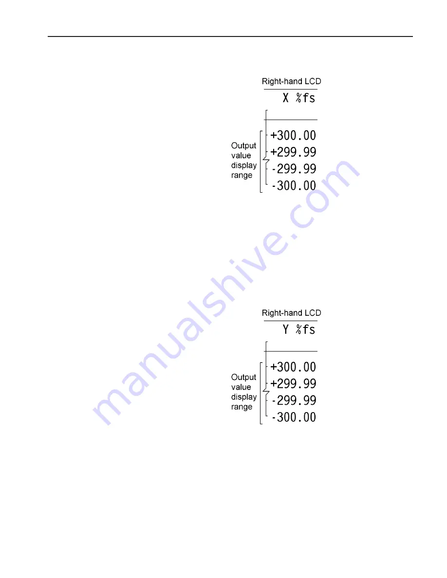
X %fs

Figure 5-27, X Output as % Full-Scale

Shows the X output as a percentage of the selected full-scale sensitivity setting.
Hence if the sensitivity setting were 100 mV and a 50 mV signal were applied, with
the instrument’s reference phase adjusted for maximum X output, the display would
read 50.00 %

Y %fs

Figure 5-28, Y Output as % Full-Scale

Shows the Y output as a percentage of the selected full-scale sensitivity setting.
Hence if the sensitivity setting were 100 mV and a 50 mV signal were applied, with
the instrument’s reference phase adjusted for maximum Y output, the display would
read 50.00 %

Summary of Contents for 7220

Page 1: ...Model 7220 DSP Lock in Amplifier Instruction Manual 190171 A MNL C Copyright 1996 EG G INSTRUMENTS CORPORATION...

Page 2: ...f Conformity This product conforms to EC Directives 89 336 EEC Electromagnetic Compatibility Directive amended by 92 31 EEC and 93 68 EEC and Low Voltage Directive 73 23 EEC amended by 93 68 EEC This...

Page 3: ...es 2 1 2 2 Initial Checks 2 3 2 2 01 Introduction 2 3 2 2 02 Procedure 2 3 Chapter Three Technical Description 3 1 Introduction 3 1 3 2 Principles of Operation 3 1 3 2 01 Block Diagram 3 1 3 2 02 Sign...

Page 4: ...o Functions 3 14 3 12 01 Introduction 3 14 3 12 02 Auto Sensitivity 3 15 3 12 03 Auto Phase 3 15 3 12 04 Auto Offset 3 15 3 12 05 Auto Measure 3 16 3 12 06 Default Setting 3 16 Chapter Four Front and...

Page 5: ...5 5 5 2 04 Control Options Menu 5 8 5 2 05 Miscellaneous Options Menu 5 10 5 2 06 RS232 Setup 1 Menu 5 11 5 2 07 RS232 Setup 2 Menu 5 12 5 2 08 RS232 Setup 3 Menu 5 13 5 2 09 GPIB Setup 1 Menu 5 14 5...

Page 6: ...01 Signal Channel 6 10 6 4 02 Reference Channel 6 13 6 4 03 Signal Channel Output Filters 6 14 6 4 04 Signal Channel Output Amplifiers 6 15 6 4 05 Instrument Outputs 6 16 6 4 06 Internal Oscillator 6...

Page 7: ...ector B 2 Appendix C DemonstrationPrograms C 1 Simple Terminal Emulator C 1 C 2 RS232 Control Program with Handshakes C 1 C 3 GPIB User Interface Program C 3 Appendix D Cable Diagrams D 1 RS232 Cable...

Page 8: ...v i TABLE OF CONTENTS...

Page 9: ...trols A good understanding of the design will enable you to get the best possible performance from the unit Chapter 4 Front and Rear Panels Describes the connectors controls and indicators which are t...

Page 10: ...a complete alphabetical listing of these commands in a single easy to use section 1 2 What is a Lock in Amplifier In its most basic form the lock in amplifier is an instrument with dual capability On...

Page 11: ...er n Dual phase demodulator with X Y and R outputs n Very low phase noise of 0 0001o rms n 5 digit output readings n Direct Digital Synthesizer DDS oscillator with variable output amplitude and freque...

Page 12: ...1 4 Chapter 1 INTRODUCTION...

Page 13: ...ted for shipping damage If any is noted EG G INSTRUMENTS should be notified immediately and a claim filed with the carrier The shipping container should be saved for inspection by the carrier 2 1 04 L...

Page 14: ...or which is located at the right hand edge of the fuse compartment Remove the barrel selector with the aid of a small screwdriver or similar tool With the barrel selector removed four numbers become v...

Page 15: ...r not that it meets specifications Each instrument receives a careful and thorough checkout before leaving the factory and normally if no shipping damage has occurred will perform within the limits of...

Page 16: ...grees 8 The right hand display should now look as follows Figure 2 4 Right hand LCD Main Display 9 Connect a BNC cable between the OSC OUT and A input connectors on the front panel 10 The right hand d...

Page 17: ...t adjustment of the AC Gain parameter described in section 3 2 04 3 2 Principles of Operation 3 2 01 Block Diagram The model 7220 utilizes two digital signal processors a microprocessor and a dedicate...

Page 18: ...Ratio CMRR defines how well the instrument rejects common mode signals applied to the A and B inputs when operating in differential input mode It is usually given in decibels Hence a specification of...

Page 19: ...ting the 3 dB point is at 50 kHz Better performance may be achieved using a separate current preamplifier such as the EG G Instruments Model 5182 3 2 03 Line Frequency Rejection Filter Following the s...

Page 20: ...reduce the AC Gain value AC Gain dB INPUT LIMIT mV 0 3000 10 1000 20 300 30 10 40 30 50 10 60 3 70 1 80 0 3 90 0 1 Table 3 1 Input Limit vs AC Gain Further information on the control of AC Gain is gi...

Page 21: ...ilter but typically the noise penalty is negligible It should be noted that the dynamic range of a lock in amplifier is normally so high that practical anti alias filters are not capable of completely...

Page 22: ...lator output The normal operating mode of the instrument incorporates two reference frequency ranges namely the baseband from 1 mHz to 60 kHz and the highband from 60 kHz to 120 kHz Different hardware...

Page 23: ...tive detector Consequently it is affected by both the reference phase shifter and harmonic controls of the reference channel For example if an external reference at 1 kHz were applied the unit were se...

Page 24: ...ratus The microprocessor has access to memory which may be used for storage of the instrument s outputs as curves prior to transferring them to a computer via the computer interfaces In addition to us...

Page 25: ...ted in section 3 2 04 the best performance is obtained by making the AC Gain value as large as possible without causing amplifier overload Note that the demodulator gain is adjusted automatically when...

Page 26: ...cuits in the reference channel In external reference operation the processor uses the reference frequency meter to monitor the reference frequency and updates these parameters when a change of about 2...

Page 27: ...the sample to be measured Other examples occur in derivative spectroscopy where a small modulation is applied to the angle of the grating in optical spectroscopy or to the applied magnetic field in ma...

Page 28: ...se Response IIR filters When the reference frequency is below 10 Hz the synchronous filter option is available This means that the actual time constant of the filter is not generally the selected valu...

Page 29: ...e Note that unlike other forms of zero error this is not a constant quantity which can be subtracted from all readings because when the square root of the sum of the squares of the required outputs be...

Page 30: ...s switched off When the instrument is switched on again the settings are restored but with the following exceptions a The signal channel reverts to AC coupling b The GPIB mask byte is set to zero c Th...

Page 31: ...which is known to be of the required phase It usually gives very good results provided that the X and Y channel outputs are steady when the procedure is called If a zero error is present it must be nu...

Page 32: ...led The Auto Sensitivity function also adjusts the AC Gain if required The Auto Measure function is intended to give a quick setting of the instrument which will be approximately correct in typical si...

Page 33: ...input connector for use in single ended and differential voltage mode The B I connector is the signal input connector for use in differential voltage mode A B and is also the signal input connector wh...

Page 34: ...display shows two of the possible range of controls and their present settings one on the upper menu line and one on the lower see figure 4 4 Figure 4 4 Main Display Left hand LCD To select a given c...

Page 35: ...digits see figures 4 5 and 4 6 Step 2 With the cursor visible repeating step 1 causes the cursor to move to the left When the cursor reaches the most significant digit available left end of control s...

Page 36: ...s from the power up display default press the key marked MENU once Note On early units this key was labelled AUTO The left hand LCD now changes to that shown in figure 4 7 Figure 4 7 Auto Functions Me...

Page 37: ...ternal Reference frequency 4 1 08 Right hand LCD Display Panel This panel is normally used to display two out of the set of fourteen possible instrument outputs with the keys on each side of it being...

Page 38: ...cale Figure 4 9 Main Display Right hand LCD 4 2 Rear Panel Figure 4 10 Model 7220 Rear Panel Layout As shown in figure 4 10 the line power switch line power voltage selector two RS232 connectors a GPI...

Page 39: ...evels connector specifications timing and handshake requirements 4 2 06 DIGITAL OUTPUTS Connector This connector provides eight TTL output lines each of which can be set high or low by the use of a fr...

Page 40: ...ut voltages are sampled and held when the ADC is triggered and several different trigger modes are available These modes can be set either from the front panel or by using a remote computer command Th...

Page 41: ...l with only a few keys Furthermore this design makes it very easy to introduce new features or improve existing ones without the limitation resulting from a fixed front panel layout The following sect...

Page 42: ...in amplifier s signal channel input are displayed Changes to the setting of these controls can be made by using the ADJUST keys adjacent to the appropriate LCD Input Mode This control has four settin...

Page 43: ...ls of the A and B I connectors are connected to chassis ground and the signal channel input is DC coupled Gnd AC The shells of the A and B I connectors are connected to chassis ground and the signal c...

Page 44: ...uitable for use with reference frequencies above 300 mHz the lock in amplifier s reference should be applied to the front panel REF IN connector A wide variety of signal waveforms may be employed but...

Page 45: ...set to 1st the signal at the OSC OUT connector will be at the same frequency as the applied reference but if set to 2nd or 3rd then the output will be at two or three times the reference frequency res...

Page 46: ...the CH1 connector and the right hand ones select that at the CH2 connector Each output may be set to one of the following settings X When set to X the corresponding rear panel CH1 CH2 connector will o...

Page 47: ...anel CH1 CH2 connector will output a voltage related to the PHA deg front panel display as follows PHA deg CH1 2 Voltage 360 9 0 V 180 0 0 V 0 9 0 V NOISE When set to NOISE the corresponding rear pane...

Page 48: ...ficant gain and phase errors when measuring signals in the frequency range from 5 Hz to 500 Hz Instruments manufactured after June 1996 which are fitted with the updated filter hardware offer four pos...

Page 49: ...ntrol affects the output time constants and has two settings SYNC When set to SYNC the actual time constant used is chosen to be some multiple of the reference frequency period In this mode the output...

Page 50: ...te EXTERNAL In this setting ADC conversions are started by an external trigger signal applied to the rear panel TRIG connector The other eight settings of this control BURST 2 to BURST 9 are only mean...

Page 51: ...bits per second Format There are four data formats available 7D 1P Sets up 7 Data Bits 1 Parity bit 1 Parity ON 8D 1P Sets up 8 Data Bits 1 Parity bit 1 Parity ON 8D 0P Sets up 8 Data Bits 0 Parity bi...

Page 52: ...also be used to signal overload conditions see section 6 3 13 for further information OFF No prompt character is sent Echo This function can be switched ON or OFF see section 6 3 08 for further infor...

Page 53: ...tup menu with controls affecting the RS232 interface is shown in figure 5 9 Address This control sets the RS232 address which is used when daisy chaining other compatible instruments Each instrument u...

Page 54: ...e controlling computer the completion of transmission of a response to a command Three choices are available CR LF A carriage return followed by a line feed are transmitted at the end of a response st...

Page 55: ...arameter error 3 8 reference unlock 4 16 overload 5 32 auto mode active or new ADC values available after external trigger 6 64 asserted SRQ 7 128 data available Hence for example if the SRQ mask byte...

Page 56: ...can range from 0 to 255 This decimal value may be set using the left hand display so that for example if it were 0 the eight output lines would all be low whereas if set to 255 then they would all be...

Page 57: ...ment over from another user Note that on completion the instrument will leave the setup menu mode and revert to the main display mode A listing of the settings invoked by the use of this function can...

Page 58: ...if the magnitude output is greater than 90 of full scale or reducing the range if the magnitude output is less than 30 of full scale After the Auto Sensitivity function is called Auto Sensitivity ope...

Page 59: ...in general display a non zero Y output value 5 Remove the source of input signal again 6 Execute a second Auto Offset operation which will reduce the X and Y outputs to zero at the new reference phase...

Page 60: ...cue operation to bring the instrument into a well defined state when it is giving unexpected results The length of the above list demonstrates that one or more items can easily be overlooked if perfor...

Page 61: ...ent input mode the instrument s full scale current sensitivity may be set to any value between 20 fA and 1 A wide bandwidth mode or 20 fA and 10 nA low noise mode in a 1 2 5 sequence Figure 5 16 Sensi...

Page 62: ...ble at all full scale sensitivity settings Figure 5 18 AC Gain Control Time Constant The time constant of the output filters is set using this control The settings between 10 s and 640 s are in a bina...

Page 63: ...ts at the FAST X and FAST Y connectors which are fixed at 6 dB octave Figure 5 20 Output Filter Slope Control Oscillator Frequency The frequency of the instrument s internal oscillator may be set usin...

Page 64: ...on Adjustment is faster if use is made of the Active Cursor control see section 4 1 04 Figure 5 22 Internal Oscillator Amplitude Control DAC 1 This control sets the voltage appearing at the rear panel...

Page 65: ...4 Figure 5 24 DAC 2 Output Control Offset This control allows an output offset to be added to the X output Y output neither or both outputs The actual value of offset applied which may range from 300...

Page 66: ...n the upper line and the output value on the lower line Selection of the required output type is made using the upper SELECT keys on each side of the right hand display Each press of the key advances...

Page 67: ...V signal were applied with the instrument s reference phase adjusted for maximum X output the display would read 50 00 Y fs Figure 5 28 Y Output as Full Scale Shows the Y output as a percentage of the...

Page 68: ...read 50 00 Noise fs Figure 5 30 Noise Output as Full Scale Shows the noise accompanying the signal in a bandwidth defined by the setting of the output filter time constant where it is assumed that th...

Page 69: ...hase where phase tan 1 Y output X output in degrees Reference Frequency Figure 5 32 Reference Frequency Display Shows the reference frequency at which the lock in amplifier is operating Note that the...

Page 70: ...ignal were applied with the instrument s reference phase adjusted for maximum X output the display would read 50 00 mV Y Volts or Amps Figure 5 34 Y Output in Volts or Amps Shows the Y output directly...

Page 71: ...100 mV and a 50 mV signal were applied regardless of the setting of the instrument s reference phase the display would read 50 00 mV Noise in Volts or Amps per Root Hertz Figure 5 36 Noise Output in V...

Page 72: ...utput ADC1 Input usually used to compensate for source intensity fluctuations in optical experiments Log Ratio Figure 5 38 Log Ratio Output Shows the logarithm to base 10 of the ratio where ratio X ou...

Page 73: ...NT PANEL OPERATION ADC1 Volts Figure 5 39 ADC 1 Input Shows the voltage applied to the rear panel ADC1 auxiliary input ADC2 Volts Figure 5 40 ADC 2 Input Shows the voltage applied to the rear panel AD...

Page 74: ...on on the LCD display of all outputs which would be affected such as X fs or MAG fs is alternated with the warning message OFFSET Y Offset Figure 5 42 Y Output Offset Control This control allows the Y...

Page 75: ...t your signal source to the relevant A and or B I input connector s Selection of Reference Mode The default setting function will have set the reference mode to internal which assumes that the interna...

Page 76: ...5 36 Chapter 5 FRONT PANEL OPERATION...

Page 77: ...anel may also be read remotely When operated via the interfaces the following features are also available 6 2 02 Curve Storage A 32768 point memory is included in the instrument This may be used as a...

Page 78: ...written for an application it can also be used in the direct or terminal mode In this mode the user enters commands on a keyboard and reads the results on a video screen The simplest way to establish...

Page 79: ...adjusted by means of the RS command In order to achieve satisfactory operation the RS232 settings must be set to exactly the same values in the terminal or computer as in the lock in amplifier 6 3 03...

Page 80: ...to type in 6 3 07 GPIB Interface General Features The GPIB is a parallel digital interface with 8 bidirectional data lines and 8 further lines which implement additional control and communication fun...

Page 81: ...ch are constantly asserted Note that some computer applications require one or more of the computer s RS232 handshake lines to be asserted If this is the case and if the requirement cannot be changed...

Page 82: ...set to a wide variety of configurations The selected GPIB termination option applies also to the output termination of any responses sent back by the lock in amplifier to the controller i e the lock...

Page 83: ...1E2 OF 1 001E 02 OF 1001E 1 6 3 11 Delimiters Any response transmissions consist of one or two numbers followed by a response terminator Where the response of the lock in amplifier consists of two num...

Page 84: ...alternatively if an overload or reference unlock is currently being reported by the front panel indicators the prompt is ASCII 63 Otherwise the prompt is ASCII 42 These error conditions correspond to...

Page 85: ...ible for asserting the SRQ line The status byte of that instrument is then further tested in order to discover the reason for the service request and to take appropriate action In the model 7220 the a...

Page 86: ...o B inputconnector If n 0 then the input configuration is determined by the VMODE command If n 0 then current mode is enabled irrespective of the VMODE setting VMODE n Voltage input configuration The...

Page 87: ...200 fA 14 50 V 50 pA 500 fA 15 100 V 100 pA 1 pA 16 200 V 200 pA 2 pA 17 500 V 500 pA 5 pA 18 1 mV 1 nA 10 pA 19 2 mV 2 nA 20 pA 20 5 mV 5 nA 50 pA 21 10 mV 10 nA 100 pA 22 20 mV 20 nA 200 pA 23 50 mV...

Page 88: ...frequency rejection filter control In instruments manufactured prior to June 1996 the value of n sets the mode of the line frequency notch filter according to the following table n Selection 0 Off 1 O...

Page 89: ...rce control Internal External The value of n sets the reference input mode according to the following table n Selection 0 INT internal 1 EXT LOGIC external rear panel TTL input 2 EXT external front pa...

Page 90: ...In floating point mode the frequency is in Hz LOCK System lock control Updates all frequency dependent gain and phase correction parameters 6 4 03 Signal Channel Output Filters SLOPE n Output low pass...

Page 91: ...er number of reference cycles If T is greater than 1 cycle the time constant is between T 2 and T The parameter n has the following significance n Effect 0 Synchronous time constant disabled 1 Synchro...

Page 92: ...H2 connectors according to the following table n2 Signal 0 X FS 1 Y FS 2 Magnitude FS 3 Phase 1 9 V 180 9 V 180 4 Phase 2 9 V 360 9 V 0 5 Noise FS 6 Ratio 1000 X ADC 1 n1 is compulsory and is either 1...

Page 93: ...ADC1 where X is the value that would be returned by the X command and ADC1 is the value that would be returned by the ADC1 command In floating point mode the RT command reports a number equivalent to...

Page 94: ...g the STAR command to specify the output s required and invoked by sending an asterisk ASCII 42 to request the data The data returned is specified by the value of n as follows n Data returned by comma...

Page 95: ...ge of n is 0 to 1 2E5 SYNCOSC n Synchronous oscillator demodulator monitor control This control operates only in external reference mode The parameter n has the following significance n Effect 0 Synch...

Page 96: ...epending on the value of n according to the following table n Frequency sweep status 0 Stop Pause 1 Run When a frequency sweep has been defined applying SWEEP 1 will start it The sweep will continue u...

Page 97: ...and ADC1 and ADC2 4 Burst mode variable rate triggered by command ADC1 only 5 Burst mode variable rate triggered by command ADC1 and ADC2 6 Burst mode fixed rate External trigger rear panel TRIG input...

Page 98: ...odes the sampling speed is set by the BURSTRATE command BURSTRATE n Sets the burst mode sampling rate for ADC1 and ADC2 n sets the sample rate for the Variable Rate burst modes according to the follow...

Page 99: ...nd 14 16384 Reference frequency bits 0 to 15 mHz 15 32768 Reference frequency bits 16 to 32 mHz 32768 points are available for data storage shared equally between the specified curves For example if a...

Page 100: ...ate of data storage to the curve buffer to 800 Hz However this only allows storage of the X and Y outputs There is no need to issue a CBD 3 command to set this up since it happens automatically when a...

Page 101: ...the NC command and also whenever a CBD or LEN command is applied without parameters Third value Status Byte The same as the response to the ST command The number returned is the decimal equivalent of...

Page 102: ...ing curve is selected for transfer When a bit is negated the curve is not transferred The bit corresponding to each curve is shown in the table below Bit Decimal value Curve and output range 0 1 X Out...

Page 103: ...sing this command with the GPIB interface the serial poll must be used After sending the DCT command perform repeated serial polls until bit 7 is set indicating that the instrument has an output waiti...

Page 104: ...daisy chained with other compatible instruments this command will change which instrument is addressed All daisy chained instruments receive commands but only the currently addressed instrument will i...

Page 105: ...range 0 to 255 REMOTE n Remote only front panel lock out control Allowed values of n are 0 and 1 When n is equal to 1 the lock in amplifier enters remote only mode in which the front panel control fun...

Page 106: ...nal Recovery In a typical simple experiment the computer is used to set the instrument controls and then to record the chosen outputs perhaps as a function of time At sampling rates of up to a few poi...

Page 107: ...he internal curve buffer or oscillator frequency sweep generator The commands to achieve this would therefore be similar to the following sequence IE 0 Set reference mode to internal VMODE 1 Single en...

Page 108: ...i e bits 0 1 and 4 LEN 1000 Number of points 100 Hz 10 seconds STR 10 Store a point every 10 ms 1 100 Hz The data is acquired by issuing TD Acquires data As the acquisition is running the M command r...

Page 109: ...plifier s internal oscillator output signal is fed via the filter stage under test to the signal input The oscillator frequency is stepped between a lower and an upper frequency and the signal magnitu...

Page 110: ...he time set by the SRATE and STR commands This gives sufficient time for the instrument output to stabilize after each change of frequency If the commands were used in the reverse order i e SWEEP 1 TD...

Page 111: ...g analog panel meter Menu system with dynamic key function allocation Signal Channel Voltage Inputs Modes A only or Differential A B Full scale Sensitivity 20 nV to 1 V in a 1 2 5 sequence Dynamic Res...

Page 112: ...acy midband Low Noise 0 6 typ Wide Bandwidth 0 6 typ Line Filter attenuates 50 60 100 120 Hz Grounding BNC shields can be grounded or floated via 1 k to ground Reference Channel TTL Input rear panel F...

Page 113: ...ng Description 2 18 bit ADCs driving two DSP elements managed by a powerful 68000 series host processor Output Zero Stability Digital Outputs No zero drift on all settings Displays No zero drift on al...

Page 114: ...aximum Input 10 V Resolution 1 mV Accuracy 0 2 Input Impedance 1 M 30 pF Sample Rate ADC 1 only 40 kHz max ADC 1 and 2 13 kHz max Trigger Mode Int ext or burst Trigger input TTL compatible Outputs CH1...

Page 115: ...ompatible Power Low Voltage 15 V at 100 mA rear panel DIN connector for powering EG G preamplifiers Data Storage Data Buffer Size 32k 16 bit data points may be organized as 1 32k 2 16k 3 10 6k 4 8k et...

Page 116: ...A 6 Appendix A SPECIFICATIONS General Dimensions Width 432 mm 17 Depth 415 mm 16 4 Height With feet 74 mm 2 9 Without feet 60 mm 2 4 Weight 7 4 kg 16 3 lb...

Page 117: ...ector Female PIN FUNCTION COMMENT 2 RXD Data In 3 TXD Data Out 5 GND Signal Ground 7 RTS Always at 12 V All other pins are not connected B 2 Preamplifier Power Connector Pinout Figure B 2 Preamplifier...

Page 118: ...via the computer interfaces each line can drive 3 LSTTL loads This connector mates with a 20 pin IDC Header Plug The pinout is as follows PIN FUNCTION 1 GROUND 2 GROUND 3 D0 4 GROUND 5 D1 6 GROUND 7...

Page 119: ...EN PRINT 1 B 140 LL LOC 1 150 IF LL 0 THEN A INPUT LL 1 PRINT A 160 WEND 170 180 PRINT ERROR NO ERR RESUME C 2 RS232 Control Program with Handshakes RSCOM2 BAS is a user interface program which illust...

Page 120: ...er 250 A INPUT 1 1 read input buffer 260 IF A C THEN PRINT handshake error input byte should be echo 270 NEXT J1 next byte to be sent or 280 RETURN return if no more bytes 290 300 310 read response 32...

Page 121: ...ended for incorporation in the user s own programs 10 GPCOM 9 Feb 96 20 the following three lines and BIB M are supplied by the 30 manufacturer of the GPIB card must be correct version 40 CLEAR 60000...

Page 122: ...te A to bus 390 S 0 initialize S 400 WHILE S AND 1 0 while command not complete 410 GOSUB 530 serial poll returns S 420 IF DS THEN PRINT S S 430 IF S AND 128 THEN GOSUB 500 PRINT B read bus into B and...

Page 123: ...s used on the connector which goes to the computer One has 9 pins and the other 25 both are null modem also called modem eliminator cables in that some of the pins are cross connected Users with reaso...

Page 124: ...D 2 Appendix D CABLE DIAGRAMS Figure D 2 Interconnecting RS232 Cable Wiring Diagram...

Page 125: ...heir default settings then communication will be lost AQN Auto Phase auto quadrature null The instrument adjusts the reference phase to maximize the X output and minimize the Y output signals AS Perfo...

Page 126: ...dified accordingly by replacing the 16 000 000 figure with 16 384 000 For example when n 20 the sample rate will be 24 353 Hz for ADC1 for an instrument with a 16 0 MHz crystal and 24 937 Hz for a uni...

Page 127: ...ength which cannot therefore be longer than 32768 divided by the number of curves selected If more curves are requested than can be stored with the current buffer length then the buffer length will be...

Page 128: ...it is an integer in the range 12000 to 12000 corresponding to voltages from 12 000 V to 12 000 V In floating point mode it is in volts DC n Dump acquired curve s to computer In fixed point mode causes...

Page 129: ...responding curve is selected for transfer When a bit is negated the curve is not transferred The bit corresponding to each curve is shown in the table below Bit Decimal value Curve and output range 0...

Page 130: ...new value is available The loop should continue until bit 1 is set indicating that the transfer is completed DD n Define delimiter control The value of n which can be set to 13 or 32 to 125 determines...

Page 131: ...ction 0 Ground 1 Float connected to ground via a 1 k resistor FNF n Reference harmonic mode control The value of n sets the reference channel to one of the NF modes or restores it to the default F mod...

Page 132: ...ihertz In floating point mode n1 is in hertz The range of n1 is 0 to 10 kHz FSTOP n Oscillator frequency sweep stop frequency Sets the stop frequency for a subsequent sweep of the internal oscillator...

Page 133: ...t is connected to a current or a voltage preamplifier The value of n sets the input mode according to the following table n Input mode 0 Current mode off voltage mode input enabled 1 High bandwidth HB...

Page 134: ...o this date Units made after June 1996 respond in addition to the command LINE50 which sets the notch filter centre frequency LINE50 n Signal channel line frequency rejection filter centre frequency c...

Page 135: ...r is incremented each time a TD is completed and each time a full cycle is completed on a TDC acquisition It is zeroed by the NC command and also whenever a CBD or LEN command is applied without param...

Page 136: ...Bit 1 CH1 output overload 120 FS Bit 2 CH2 output overload 120 FS Bit 3 Y output overload 300 FS Bit 4 X output overload 300 FS Bit 5 not used Bit 6 input overload Bit 7 reference unlock NC New curve...

Page 137: ...n the range 18000 In floating point mode causes the lock in amplifier to respond with the signal phase in degrees REFP n Reference phase control In fixed point mode n sets the phase in millidegrees in...

Page 138: ...ty 3 echo disabled echo enabled 4 prompt disabled prompt enabled RT Ratio output In integer mode the RT command reports a number equivalent to 1000 X ADC1 where X is the value that would be returned b...

Page 139: ...21 10 mV 10 nA 100 pA 22 20 mV 20 nA 200 pA 23 50 mV 50 nA 500 pA 24 100 mV 100 nA 1 nA 25 200 mV 200 nA 2 nA 26 500 mV 500 nA 5 nA 27 1 V 1 A 10 nA Floating point mode can only be used for reading t...

Page 140: ...Data returned by command 0 X 1 Y 2 MAG 3 PHA 4 ADC1 5 XY 6 MP 7 ADC1 ADC2 Transfer command This command establishes the high speed transfer mode Use the STAR command to set up the desired response to...

Page 141: ...ll be the time constant actually used SWEEP n Oscillator frequency sweep start Stop Starts stops the internal oscillator frequency sweep depending on the value of n according to the following table n...

Page 142: ...External trigger rear panel TRIG input ADC1 only 7 Burst mode fixed rate External trigger rear panel TRIG input ADC1 and ADC2 8 Burst mode variable rate External trigger rear panel TRIG input ADC1 onl...

Page 143: ...value of n sets the time constant of the output according to the following table n time constant 0 10 s 1 20 s 2 40 s 3 80 s 4 160 s 5 320 s 6 640 s 7 5 ms 8 10 ms 9 20 ms 10 50 ms 11 100 ms 12 200 ms...

Page 144: ...de 1 A input only 3 A B differential mode Note that the IMODE command takes precedence over the VMODE command X X output In fixed point mode causes the lock in amplifier to respond with the X demodula...

Page 145: ...YOF n1 n2 Y output offset control The value of n1 sets the status of the Y offset facility according to the following table n1 Selection 0 Disables offset facility 1 Enables offset facility The range...

Page 146: ...E 22 Appendix E ALPHABETICAL LISTING OF COMMANDS...

Page 147: ...values Full scale sensitivity 500 mV AC Gain 0 dB Time constant 100 ms Slope 12 dB octave Oscillator frequency 1000 000 Hz Oscillator amplitude 0 500 mV rms DAC1 output 0 000 V DAC2 output 0 000 V Out...

Page 148: ...Front panel lights On Display contrast 0 RS232 interface settings Baud rate 9600 Data bits 7 Stop bits 1 Parity Even Prompt character On Character echo On Delimiter 044 Address 1 GPIB interface setti...

Page 149: ...duction 3 14 menu 5 18 AUTO key 4 4 AUTO menu 4 4 Auto repeat 4 3 AUTOMATIC n command 6 12 E 1 AUX RS232 connector 4 7 Auxiliary ADCs 3 8 Auxiliary RS232 interface 6 4 AXO command 6 16 E 2 Baseband re...

Page 150: ...e 3 9 ENBW command 6 18 E 6 Equivalent noise bandwidth 3 14 EVENT n command 6 24 E 6 EX n command 6 16 E 7 External reference 5 4 External reference mode 3 6 FAST X connector 4 8 output 3 7 FAST Y con...

Page 151: ...AG command 6 17 E 11 Main Display mode 5 1 5 20 Main display mode 4 4 Main microprocessor 3 8 MENU key 4 4 Microsoft Windows Terminal program 6 2 Miscellaneous options menu 5 10 MP command 6 17 E 11 M...

Page 152: ...17 E 14 SAMPLE n command 6 13 E 14 Sample rate control 5 17 SELECT keys 4 2 5 1 SEN n command 6 11 E 15 Sensitivity control 5 20 SET key 4 5 Setup menu mode 4 4 5 1 SIG MON connector 3 4 4 7 Signal ch...

Page 153: ...ifier 1 2 X output 5 6 X fs display 5 27 X Y demodulation functions 3 7 X in volts amps display 5 30 X output offset level control 5 34 X command 6 16 E 20 XOF n1 n2 command 6 15 E 20 XY command 6 17...

Page 154: ...Index 6 INDEX...

Page 155: ...ANY AND ALL OTHER WARRANTIES OR REPRESENTATIONS EXPRESSED IMPLIED OR STATUTORY INCLUDING MERCHANTABILITY AND FITNESS FOR A PARTICULAR PURPOSE AS WELL AS ANY AND ALL OTHER OBLIGATIONS OR LIABILITIES O...

Reviews: