background image

v

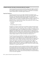
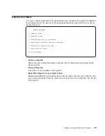
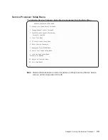
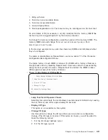
OS Surveillance Setup Menu

This menu can be used to set up operating system (OS) surveillance.

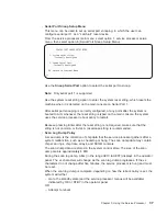
OS Surveillance Setup Menu

1. Surveillance:

Currently Enabled

2. Surveillance Time Interval:

2 minutes

3. Surveillance Delay:

2 minutes

98. Return to Previous Menu

0>

– Surveillance

Can be set to Enabled or Disabled.

– Surveillance Time Interval

Can be set to any number from 2 through 255.

– Surveillance Delay

Can be set to any number from 0 through 255.

Refer to “Service Processor System Monitoring - Surveillance” on page 65 for more
information about surveillance.

v

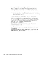
Reset Service Processor

If this option is selected, entering

Y

causes the service processor to reboot.

v

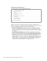
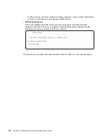
Reprogram Flash EPROM Menu

This option requires a diskette drive to be installed in the system. If this option is
selected, and no diskette drive is present in the system, the service processor will
indicate

Not Supported

on the screen.

This option updates the system EPROMs. After entering

Y

to indicate that you want

to continue, you are prompted to enter the update diskettes. Follow the instructions
on the screen. When the update is complete, the service processor reboots.

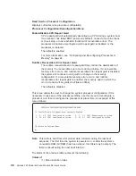
All system EPROMs that can be reprogrammed are updated at the same time and
are as follows:

– System power control network programming

– Service processor programming

– System firmware programming

– Run-Time Abstraction Services

36

pSeries 630 Model 6C4 and Model 6E4 User’s Guide

Summary of Contents for 6.00E+04

Page 1: ...pSeries 630 Model 6C4 and Model 6E4 User s Guide SA38 0606 00 ERserver IBM...

Page 2: ......

Page 3: ...pSeries 630 Model 6C4 and Model 6E4 User s Guide SA38 0606 00 ERserver IBM...

Page 4: ...ts to Information Development Department H6DS 905 6C006 11501 Burnet Road Austin Texas 78758 3493 To send comments electronically use this commercial internet address aix6kpub austin ibm com Any infor...

Page 5: ...ly 2 Keyboard 2 Mouse 2 Operator Panel 3 Input Output Ports 3 Security Features 4 Front View 4 Rear View 6 Operator Panel 8 Chapter 2 Using the System 9 Starting the System Unit 9 Stopping the System...

Page 6: ...al Port Speed Setup Menu 54 Telephone Number Setup Menu 55 Call Out Policy Setup Menu 56 Customer Account Setup Menu 57 Call out Test Menu 57 Service Processor Parameters in Service Mode Full System P...

Page 7: ...System Management Services 89 Chapter 5 Using the Standalone and Online Diagnostics 91 Standalone and Online Diagnostics Operating Considerations 91 Selecting a Console Display 91 Identifying the Ter...

Page 8: ...Display or Change Diagnostic Run Time Options 123 Display Previous Diagnostic Results 124 Display Resource Attributes 124 Display Service Hints 124 Display Software Product Data 125 Display System En...

Page 9: ...ice Aid 148 Command Examples 149 7318 Serial Communications Network Server Service Aid 149 Chapter 7 Verifying the Hardware Operation 151 Running System Verification When Not Connected to an Hardware...

Page 10: ...ial Port Configuration 181 Appendix F Modem Configurations 183 Sample Modem Configuration Files 183 Generic Modem Configuration Files 183 Specific Modem Configuration Files 183 Configuration File Sele...

Page 11: ...st not be in direct contact with the rack v Care should be taken to ensure that a hazardous condition is not created due to uneven mechanical loading when installing this unit in a rack If the rack ha...

Page 12: ...ng or removing signal cables ensure that the power cables for the system unit and all attached devices are unplugged When adding or removing any additional devices to or from the system ensure that th...

Page 13: ...ion numbers and approval information CAUTION All IBM laser modules are designed so that there is never any human access to laser radiation above a class 1 level during normal operation user maintenanc...

Page 14: ...xii pSeries 630 Model 6C4 and Model 6E4 User s Guide...

Page 15: ...es or component failures must verify the accuracy of operations performed and data saved or transmitted by the system at or near the time of the outage or failure In addition users must establish proc...

Page 16: ...xiv pSeries 630 Model 6C4 and Model 6E4 User s Guide...

Page 17: ...l 6E4 Service Guide order number SA38 0604 contains reference information maintenance analysis procedures MAPs error codes removal and replacement procedures and a parts catalog v The RS 6000 Eserver...

Page 18: ...Computing Web site gives ergonomic guidelines to help you understand the ergonomic considerations that you should know when working at a computer workstation The address is http www us pc ibm com heal...

Page 19: ...e these slots with PCI adapters that do not demand high performance All slots are capable of running either 64 bit or 32 bit adapters However a 32 bit adapter operates in a 32 bit mode and shows no pe...

Page 20: ...ation media v Media bay 2 can accommodate a DVD RAM diskette drive or tape drive Contact your sales representative to check the availablility of 8 mm tape drives Four hot plug disk drive bays v 18 2 G...

Page 21: ...chassis Current usage for the serial port connectors are as follows Serial Port Number Location Applicable Usage Examples Serial Port 1 S1 Front Operator Panel Service Agent PDA System Management Appl...

Page 22: ...is usually available to all users who are allowed to power on the system v Privileged access password Set from the service processor menus or from System Management Services SMS utilities Used by the...

Page 23: ...Model 6E4 1 Operator Panel 2 Front Serial Connector 3 IDE CD ROM Drive 4 Media Bay 5 Hot Plug Disk Drives Chapter 1 Introducing the System 5...

Page 24: ...tor 2 4 System Power Control Network Connector SPCN2 13 Serial Connector 3 5 System Power Control Network Connector SPCN1 14 Serial Connector 1 6 Parallel Connector 15 Mouse Connector 7 Hardware Manag...

Page 25: ...nector 2 4 System Power Control Network Connector SPCN2 13 Serial Connector 3 5 System Power Control Network Connector SPCN1 14 Serial Connector 1 6 Parallel Connector 15 Mouse Connector 7 Hardware Ma...

Page 26: ...Display 2 Power On LED 7 FS1 Front Serial Connector RJ48 Connector 3 Attention LED 8 Service Processor Reset Switch Pinhole 4 SCSI Port Activity LED 9 System Reset Button 5 Ethernet Port Activity LED...

Page 27: ...If the Power On LED does not come on and there is no indication of power when you press the Power On button go to Chapter 8 Hardware Problem Determination on page 157 Stopping the System Unit Attenti...

Page 28: ...source 3 Attention LED Normal State LED is off 4 SCSI Port Activity Normal State LED is on when there is SCSI activity 5 Ethernet Port Activity Normal State LED is on when there is Ethernet activity 6...

Page 29: ...Electrical power is present v Activity is occuring on a link The system could be sending or receiving information Amber colored LEDs indicate a fault or identify condition If your system or one of th...

Page 30: ...op Green 1x No Input AC Input Good N A Fault Power Supply Front Top Amber 1x Normal N A Identify Power Control Comm Failed 25 Hz DC Output Good Power Supply Front Top Green 1x DC Off DC Good Standby D...

Page 31: ...e Amber 1x Normal Identify Processor Board Identify Processor Housing Top Amber 1x Normal Identify PCI Riser Card Identify PCI Riser Card Amber 1x Normal Identify Disk Drive Backplane No LED PCI Adapt...

Page 32: ...Ethernet Port Ethernet 1 Ethernet 2 Mode Chassis Rear Green 2x 10 Mbit Mode 100 Mbit Mode Activity Chassis Rear Green 2x No Activity Activity Activity Operator Panel Green 1x No Activity Activity For...

Page 33: ...colored LED 2 Call for service You will be given the choice to replace the failing component yourself or have a service representative replace it for you If you decide to replace the failing component...

Page 34: ...nctions depend upon the application used v Numeric keypad is arranged like a calculator to help when typing numbers On all of the keyboards you can adjust the tilt position for typing comfort To tilt...

Page 35: ...ur selection or choosing a command The precise function of your mouse depends on the software you are using The mouse cable plugs into the mouse connector at the rear of the system Handling the Mouse...

Page 36: ...se the following steps to clean the mouse 1 Remove the retaining ring by turning it counterclockwise in the direction of the arrow as shown in the illustration 2 Remove the ball 3 Inspect the ball for...

Page 37: ...d capacity Write Protecting 3 5 Inch Diskettes Write protecting diskettes is necessary so that important information is not accidentally lost When diskettes are write protected you can read informatio...

Page 38: ...features of the 40X SCSI 2 CD ROM drive and provides instructions for handling the drive and CD ROM discs The CD ROM is a half high 5 25 inch 8 bit single ended tray loading drive Its features includ...

Page 39: ...is Off Drive is in standby mode with or without a disc loaded Blinking green Any of the following v Drive tray is inserted The light blinks while the drive completes the initialization checkout v Dri...

Page 40: ...e surface v Do not store or place the compact disc in direct sunlight v Do not use benzene thinners or other cleaners to clean the compact disc v Do not bend the compact disc Other Handling Considerat...

Page 41: ...ghtened end of a paper clip into the emergency eject hole until you feel some resistance If you are not sure where the emergency eject hole is located see Front View of CD ROM Drive on page 21 3 Conti...

Page 42: ...restart until the system either restarts successfully or a predetermined retry threshold is reached In the event the service processor is unsuccessful in bringing the system online or in the event tha...

Page 43: ...system as the problem reporting server A single system accessible over the user network can be used as the central server for all the other systems on the local area network LAN that are running the...

Page 44: ...26 pSeries 630 Model 6C4 and Model 6E4 User s Guide...

Page 45: ...sor is controlled by firmware and does not require the AIX operating system to be operational to perform its tasks The service processor menus allow you to configure service processor options as well...

Page 46: ...rocessor menus can be accessed remotely as follows 1 With the system powered off call in from a remote terminal 2 The service processor detects ring indicate and prompts you for a password if one is s...

Page 47: ...System Boot 5 Read Service Processor Error Logs 6 Read System POST Errors 99 Exit from Menus 0 v Power on System Allows the user to start the system using the current virtual terminal window as the a...

Page 48: ...e listed from top latest to bottom oldest This information is not stored in nonvolatile storage If the system is powered off using the power on button on the operator panel this information is retaine...

Page 49: ...en to your system during setup You need the firmware version for reference when you either update or repair the functions of your service processor The system name an optional field is the name that y...

Page 50: ...m Name 99 Exit from Menus 0 v Service Processor Setup Menu See Service Processor Setup Menu on page 33 for more information v System Power Control Menu See System Power Control Menu on page 40 for mor...

Page 51: ...nsole Mirroring Currently Enabled 4 Start Talk Mode 5 OS Surveillance Setup Menu 6 Reset Service Processor 7 Reprogram Flash EPROM Menu 8 Serial Port Snoop Setup Menu 9 Scan Log Dump Setup Menu Curren...

Page 52: ...someone entering passwords at the system the service processor commands the system to resume the initial program load IPL This action is taken based on the assumption that the system is in an adequat...

Page 53: ...rial ports The serial port from which console mirroring is enabled is referred to as the active port The mirror port is determined when keyboard input is detected from one of the other ports From this...

Page 54: ...d entering Y causes the service processor to reboot v Reprogram Flash EPROM Menu This option requires a diskette drive to be installed in the system If this option is selected and no diskette drive is...

Page 55: ...processor reboot policy to restart Because pressing Enter after the reset string is not required make sure that the string is not common or trivial A mixed case string is recommended v Scan Log Dump...

Page 56: ...type This is the default value 3 Always Selecting this option allows the service processor to record a scan log dump for all error types The scan log dump policy can also be set from the Tasks menu i...

Page 57: ...n possible a minimum number of hardware scan log rings The complete dump will take the longest time to finish it may take as long as 1 5 hours on a fully configured system Option 3 Immediate Dump can...

Page 58: ...m Boot Currently Fast Boot 7 Boot Mode Menu 98 Return to Previous Menu 99 Exit from Menus 0 v Enable Disable Unattended Start Mode Use this option to instruct the service processor to restore the powe...

Page 59: ...er on is enabled and call in is already enabled you will be asked to confirm your choice Refer to the message displayed on your screen If the ring indicate power on setting is changed you must select...

Page 60: ...boot process it attempts to reboot the number of times specified Entry values equal to or greater than 0 are valid Only successive failed reboot restart attempts are counted Use OS Defined restart po...

Page 61: ...to a system fault and you are running a full system partition you can enable the service processor to call out and report the event This option can be valuable if the number of these events becomes e...

Page 62: ...m Saved List This selection causes the system to perform a service mode boot using the service mode boot list saved in NVRAM If the system boots AIX from the disk drive and AIX diagnostics are loaded...

Page 63: ...ators from Last System Boot Displays a number of the boot progress indicators which may include Service Processor checkpoints IPL checkpoints or AIX configuration codes from the previous system boot T...

Page 64: ...uration If a recoverable memory error occurs and runtime recoverable error repeat gard is enabled the memory quad in which the error occurred will be garded out taken offline The default is disabled T...

Page 65: ...y remain online If they fail the boot testing they are deconfigured even though CPU repeat gard is disabled The failure history of each CPU is retained If a processor with a history of failures is bro...

Page 66: ...ONFIGURATION DECONFIGURATION MENU 1 3 16 00 Configured by system 2 3 17 00 Configured by system 3 3 18 00 Configured by system 4 3 19 00 Configured by system 5 4 24 00 Configured by system 6 4 25 00 C...

Page 67: ...MM with a history of failures is brought back online by disabling Repeat Gard it remains online if it passes testing during the boot process However if Repeat Gard is enabled the DIMM is taken offline...

Page 68: ...ubsystem disturbance system attention LED Use this menu to toggle the attention fault LEDs between identify blinking and off An example of this menu follows LED Indicator 1 CEC LED at location U0 1 Cu...

Page 69: ...ce processor and system firmware menus and messages are displayed LANGUAGE SELECTION MENU 1 English 2 Francais 3 Deutsch 4 Italiano 5 Espanol 98 Return to Previous Menu 99 Exit from Menus 0 Note Your...

Page 70: ...Telephone Number Setup Menu 5 Call Out Policy Setup Menu 6 Customer Account Setup Menu 7 Call Out Test 98 Return to Previous Menu 99 Exit from Menus 0 v Modem Configuration Menu see Modem Configuratio...

Page 71: ...ports with modems make your selections one port at a time Modem Configuration Menu Port 1 Modem Configuration File Name Port 2 Modem Configuration File Name To make changes First select the port and t...

Page 72: ...ower on is already enabled and you try to enable call in a message prompts you for confirmation Refer to the message displayed on the screen Serial Port Speed Setup Menu This menu allows you to set se...

Page 73: ...rmation about the format and catcher computers refer to the readme file in the AIX usr samples syscatch directory Contact your service provider for the correct service center telephone number to enter...

Page 74: ...mote timeout in seconds Currently 120 3 Remote latency in seconds Currently 2 4 Number of retries Currently 2 98 Return to Previous Menu 0 v Call Out policy can be set to first or all If call out poli...

Page 75: ...h your service provider might have access If your service provider does not use RETAIN leave these fields unassigned Call out Test Menu Tests the configuration after the modem is installed and configu...

Page 76: ...e ac loss occurred For example if the system was powered on when ac loss occurred it reboots restarts when power is restored If the system was powered off when ac loss occurred it remains off when pow...

Page 77: ...system activity see the Set Surveillance Parameters option in the SERVICE PROCESSOR SETUP MENU If OS activity stops due to a hardware or software induced failure the service processor can initiate a...

Page 78: ...e Use OS Defined restart policy is set to No OR The Use OS Defined restart policy is set to Yes and the operating system has no automatic restart policy Refer to Service Processor Reboot Restart Recov...

Page 79: ...he system see Determining the Level of Firmware on the System on page 62 General Information on System Firmware Updates All the system firmware types that can be reprogrammed are updated at the same t...

Page 80: ...is currently on the system v Looking at the top of the service processor main menu System Firmware Update Using a Locally Available Image To update the system firmware using a locally available image...

Page 81: ...progress you will see Rebooting on the display for several minutes The firmware update is complete Updating System Firmware From the Service Processor Menus This procedure requires a diskette drive t...

Page 82: ...complete the service processor resets itself and goes through a complete reboot Configuring and Deconfiguring Processors or Memory All failures that crash the system with a machine check or check sto...

Page 83: ...severity and threshold exceeded status is returned to AIX At the same time PRD marks the CPU for deconfiguration at the next boot AIX will attempt to migrate all resources associated with that proces...

Page 84: ...f time to wait from the time the operating system is started to when the first heartbeat is expected Surveillance does not take effect until the next time the operating system is started after the par...

Page 85: ...e serial port where the modem is connected v Enter the modem configuration file name v Set up site specific parameters phone numbers for call out call out policy number of call out retries and so on 3...

Page 86: ...3 Remote attachment through modem is supported on serial port 1 S1 and serial port 2 S2 System Configuration The following describes the configuration for console mirroring v Service processor v Modem...

Page 87: ...rsal time UTC which is also referred to as Greenwich mean time GMT AIX error logs have additional information available and can time stamp with local time Entering an error number provides nine words...

Page 88: ...s Indicator Log B0FF 0539 17 0538 17 0539 17 0538 17 0539 17 0581 0538 17 0539 12 0538 12 0539 0821 01 K1 00 0539 0728 01 R1 00 00 0539 0664 40 60 00 1 0 0539 0777 U0 1 P2 I1 E1 0539 0742 U0 1 P2 I2 E...

Page 89: ...mpleted The pre standby phase components are v Service Processor Initialization Service processor performs any necessary hardware and software initialization v Service Processor POST Service processor...

Page 90: ...installed so that incoming calls can be received or outgoing calls can be placed v Dial In Monitor incoming phone line to answer calls prompt for a password verify the password and remotely display th...

Page 91: ...Responding to System Processor Commands The service processor responds to any command issued by the system processor Runtime Phase This phase includes the tasks that the service processor performs du...

Page 92: ...74 pSeries 630 Model 6C4 and Model 6E4 User s Guide...

Page 93: ...splays Main Menu 1 Select Language 2 Change Password Options 3 View Error Log 4 Setup Remote IPL Initial Program Load 5 Change SCSI Settings 6 Select Console 7 Select Boot Options Navigation keys X eX...

Page 94: ...item and pressing enter if applicable or selecting a navigation key Select Language Note Your TTY must support the ISO 8859 character set to properly display languages other than English This option...

Page 95: ...t your system If you previously had set a privileged access password and want to remove it select Remove Privileged Access Password View Error Log Use this option to view or clear your system s error...

Page 96: ...net Protocol Parameters option displays the following menu IP Parameters 1 Client IP Address 000 000 000 000 2 Server IP Address 000 000 000 000 3 Gateway IP Address 000 000 000 000 4 Subnet Mask 255...

Page 97: ...on keys M return to main menu ESC key return to previous screen X eXit System Management Services Type the number of the menu item and press Enter or Select a Navigation key _ Entering adapter paramet...

Page 98: ...lex option allows you to change how the Ethernet adapter communicates with the network Full Duplex 1 Yes 2 No 3 Auto Navigation keys M return to main menu ESC key return to previous screen X eXit Syst...

Page 99: ...stem Management Services Type the number of the menu item and press Enter or Select a Navigation key _ After selecting an adapter you will be asked to set the parameters for the adapter a menu similar...

Page 100: ...reen entering those changes will not automatically update the adapter parameters screen You must go back to the adapter parameters menu to make changes Notes 1 Once the ping test is initiated it may t...

Page 101: ...Install or Boot a Device 2 Select Boot Devices 3 Multiboot Startup Navigation keys M return to main menu ESC key return to previous screen X eXit System Management Services Type the number of the menu...

Page 102: ...If a device is selected that does not reside in the system a menu with the following message displays THE SELECTED DEVICES WERE NOT DETECTED IN THE SYSTEM Press any key to continue If hard drive is s...

Page 103: ...device is selected for installing the operating system or to boot from the Select Task menu allows you to get more information about the device or to boot from that device in normal mode or service m...

Page 104: ...to previous screen X eXit System Management Services Type the number of the menu item and press Enter or Select a Navigation key _ When any of the options 1 5 is selected the Device Type screen will...

Page 105: ...d press Enter or Select a Navigation key _ Selecting Information will display a menu similar to the following for a hard disk Device Information pci 3fffdf0a000 pci 2 4 scsi 1 sd 8 0 Integrated Bootab...

Page 106: ...r or Select a Navigation key _ Restore Default Settings This option restores the boot list to the default boot list The default boot list will vary depending on the devices that are installed in the s...

Page 107: ...is invoked automatically on startup Exiting System Management Services After you have finished using the system management services type x for exit at the Utilities menu to boot your system or partiti...

Page 108: ...90 pSeries 630 Model 6C4 and Model 6E4 User s Guide...

Page 109: ...he AIX error log and certain SMIT functions are only available when diagnostics are run from the disk drive v When running online diagnostics device support for some devices may not have been installe...

Page 110: ...stic programs load The diagnostic CD ROM disc can only be ejected after the system has been powered off and then powered on standalone mode or after the diagnostics program has terminated online concu...

Page 111: ...o run diagnostics from the NIM server To verify that the client system is registered on the NIM server and diagnostic boot is enabled from the command line on the NIM server run the following command...

Page 112: ...there is a gateway either ask the system network administrator or compare the first 3 octets of the NIM server address and the client address If they are the same for example if the NIM server address...

Page 113: ...ontinue to have problems refer to Boot Problems Concerns in the service guide for the system unit Then follow the steps for network boot problems Locking and Unlocking the Electronic Service Agent If...

Page 114: ...X indicating it is locked out Use the following procedure to unlock the service agent 1 Click the Administration folder 2 Select the Lockout Machines option 3 In the Detail screen select the system yo...

Page 115: ...ics v When the diagnostics present display information through the S1 serial port certain attributes are used These attributes are set as if the diagnostics were using a 3161 display terminal Refer to...

Page 116: ...or 6 on the TTY keyboard to indicate that diagnostics should be loaded Note The term POST indicators refers to the device mnemonics that are displayed while the POST is running 6 Enter any requested...

Page 117: ...res the device not be assigned to or used by any other operation This level of testing on a disk drive might require the use of the varyoff command The diagnostics display menus to allow you to vary o...

Page 118: ...nostic controller is loaded follow the normal diagnostic instructions To run the online diagnostics in maintenance mode you must be logged in to the customer s version of the AIX operating system as r...

Page 119: ...boot 5 Select Option 98 to exit the system power control menu 6 Use the HMC to power on the managed system in a full system partition by selecting the managed system in the Contents area 7 Right click...

Page 120: ...ource on the Diagnostic Selection menu The checkout programs end with either of the following results v The Testing Complete menu displays with a message stating No trouble was found v The A Problem W...

Page 121: ...steps 1 Stop all programs including the AIX operating system get help if needed 2 Remove all tapes diskettes and compact discs 3 Turn off the system unit power 4 Turn on the system unit power 5 Inser...

Page 122: ...104 pSeries 630 Model 6C4 and Model 6E4 User s Guide...

Page 123: ...ection option from the FUNCTION SELECTION menu After a task is selected a resource menu may be presented showing all resources supported by the task A fast path method is also available to perform a t...

Page 124: ...Product Data v Display Machine Check Error Log v Display Microcode Level v Display or Change Bootlist v Display or Change Diagnostic Run Time Options v Display Previous Diagnostic Results v Display Re...

Page 125: ...stic Test List are listed If no resources are available to be added then none are listed AIX Shell Prompt Note Use this service aid in Online Service Mode only This service aid allows access to the AI...

Page 126: ...ies not console mode d devicename Specifies the device whose internal log you want to analyze for example SCRAID0 s start date Specifies all errors after this date are analyzed e end date Specifies al...

Page 127: ...of diskette being verified The program then reads all of the ID and data fields on the diskette one time and displays the total number of bad sectors found v Certify DVD RAM media This selection read...

Page 128: ...AIX command line See the following command syntax diag c d deviceName T certify Flag Description c No console mode d Specifies a device T Specifies the certify task v Format and or Erase Hardfile Atta...

Page 129: ...te If you use Format and Certify option there may be some blocks that are placed into the grown defect MAP 3 If there are bad blocks in the defect MAP record the information presented and ensure that...

Page 130: ...or recovered errors unrecovered errors and reassigned errors If these errors exceed the threshold values the user is prompted to replace the physical disk This task can be run directly from the AIX co...

Page 131: ...TTYs To determine if there are any defined TTYs select List All Defined TTYs After all defined TTYs have been removed add a new TTY and configure the Dials or LPF keys Configure ISA Adapter This task...

Page 132: ...e maximum number of attempts v Use the O S Defined Restart Policy 1 Yes 0 No When Use the O S Defined Restart Policy is set to Yes the system attempts to reboot from a crash if the operating system ha...

Page 133: ...urrently loaded on S1 Modem file currently loaded on S2 This is the name of the file that is currently loaded on serial port 1 or serial port 2 Note These settings are only shown when a modem file is...

Page 134: ...ure This is set to either First or All If the call out policy is set to First call out stops at the first successful call to one of the following numbers in the order listed 1 Service Center 2 Custome...

Page 135: ...n full machine partition This service aid monitors the system for hang conditions that is hardware or software failures that cause operating system inactivity When enabled and surveillance detects ope...

Page 136: ...onsole You can create a console configuration file that allows a terminal attached to any RS232 or RS422 adapter to be selected as a console device The default device is an RS232 TTY device attached t...

Page 137: ...e used to update to a different size drive The service aid only supports copying from a SCSI drive to another SCSI drive of similar size 2 Use the migratepv command when copying the contents to other...

Page 138: ...the old drive 3 Install the new drive in the old drive s location 4 Install any other drives that were removed into their original location To prevent problems that can occur when running this service...

Page 139: ...rmation This task displays the firmware device node information This service aid is intended to gather more information about individual or particular devices on the system The format of the output da...

Page 140: ...ocode or firmware levels of currently installed resources When the sys0 resource is selected the task displays the levels of both the system firmware and service processor firmware sys0 may not be ava...

Page 141: ...urn on or off including the Error Log Analysis ELA the default is off v Number of Days Used to Search Error Log This option allows the user to select the number of days for which to search the AIX err...

Page 142: ...g system error log This information is stored in the var adm ras directory You can run the command from the AIX command line by typing usr lpp diagnostics bin diagrpt o s mmddyy a r Flag Description o...

Page 143: ...v Warning High The sensor reading indicates a problem with the device This could become a critical problem if action is not taken Run diagnostics on sysplanar0 to determine what repair action is neede...

Page 144: ...the environmental sensors usr lpp diagnostics bin uesensor l Sensor Fan Speed Status Normal Value 2436 RPM Location Code F1 Sensor Power Supply Status Normal Value Present and operational Location Co...

Page 145: ...the adapter or device is selected the service aid provides menus to guide you in checking the current level and downloading the needed microcode This task can be run directly from the AIX command lin...

Page 146: ...to a PCI SCSI Adapter See the following command syntax for a DVD RAM attached to a PCI SCSI Adapter diag c d cdX T download s etc microcode diskette l latest previous f Flag Description c No console...

Page 147: ...spares You can run this task from the AIX command line Use the following fast path command diag T certify Format Physical Disk This selection is used to format a selected disk drive You can run this...

Page 148: ...on specify the number 0 3 of patterns to be written The patterns are written serially that is the first pattern is written to all blocks Then the next pattern is written to all blocks overlaying the p...

Page 149: ...sed due to errors accessing grown defect map Note The Erase Disk option in command line mode uses default values To selectively read or write use the diag command in console mode Hardfile Attached to...

Page 150: ...ta hard disk or removable media Generic Microcode Download The Generic Microcode Download service aid provides a means of executing a genucode script from a diskette or tape The purpose of this generi...

Page 151: ...Manager task is a SMIT menu that allows you to identify add remove or replace PCI adapters that are hot pluggable Refer to the PCI Adapter Placement Reference for information regarding slot restrictio...

Page 152: ...the customer or system administrator must be notified to quiesce the device The Configure Devices function allows a newly added adapter to be configured into the system for use This function should a...

Page 153: ...When a slot is selected for identification the visual indicator for the slot is set to the Identify state The Attach a Device to an SES Device function lists all empty hot swap slots that are availab...

Page 154: ...nning an option such as identify or remove d Indicates the SCSI device T Specifies the task to run RAID Hot Plug Devices This selection starts the PCI SCSI 2 F W RAID Adapter Service Aid Local Area Ne...

Page 155: ...cal Disk Identify This selection identifies physical disks connected to a PCI SCSI 2 F W RAID adapter You can run this task directly from the AIX command line See the following command syntax diag c d...

Page 156: ...Only supported in concurrent or service modes v Not supported from standalone diagnostics v System performance will be degraded while running the exerciser so it is recommended that customer applicati...

Page 157: ...d select and run the Error Log Analysis task If Error Log Analysis does not report a problem contact service support Exerciser Commands CMD Use the following commands as needed in the exerciser menus...

Page 158: ...and Test Diagnostic Cartridge are required to run this exerciser The actual Test Diagnostics Cartridge depends upon the specific tape device being tested The exerciser automatically rewinds the tape T...

Page 159: ...on writes all of the settings for the hardware management policies to the following file etc lpp diagnostics data hmpolicies v Restore Hardware Management Policies This selection restores all of the s...

Page 160: ...ng detected v The service aid transmitted a SCSI Inquiry Command and did not receive any response or error status back v The service aid transmitted a SCSI Inquiry Command and the adapter indicated a...

Page 161: ...tion to the screen to copy it to a DOS formatted diskette or to copy it to a file The file name LOGSENSE DAT is used when the log sense data is written to the diskette The service aid prompts for a fi...

Page 162: ...o be backed up and replaced Formatting the disk does not improve the availability of spare sectors You can run this task directly from the AIX command line See the following command syntax diag c d de...

Page 163: ...to verify the fix At this time also do a Log Repair Action if the test on the resource was good and that resource had an entry in the error log If the serviceable event was not the result of an error...

Page 164: ...for system and service processor firmware newer systems have a combined image that contains both in one image Look for additional update and recovery instructions with the update kit You need to know...

Page 165: ...le an error is reported stating additional system memory is needed After the file is copied a screen requests confirmation before continuing with the flash update When you continue with the update the...

Page 166: ...the integrity of the data on drives designated as spares v Format Physical Disk Formats a selected disk drive v Array Controller Microcode Download Allows the microcode on the 7135 controller to be u...

Page 167: ...c microcode directory l Physical disk channel ID for example 27 P Download the previous level of microcode default to latest level To format a physical disk use this command syntax diag c d deviceName...

Page 168: ...150 pSeries 630 Model 6C4 and Model 6E4 User s Guide...

Page 169: ...unit is directly attached to another system unit or attached to a network be sure communication with the other systems is stopped v This procedure requires use of all of the system resources No other...

Page 170: ...g figure shows the operator panel and the locations of operator panel components that are referred to in this procedure 1 Power On Button 6 Operator Panel Display 2 Power LED 7 FS1 Front Serial Connec...

Page 171: ...resource on the Diagnostic Selection menu The checkout programs end with either of the following results v The Testing Complete menu displays with a message stating No trouble was found v The A Proble...

Page 172: ...power control menu 6 Use the HMC to power on the managed system in a full system partition by selecting the managed system in the Contents area 7 Right click or select the desired system in the Conte...

Page 173: ...resource on the Diagnostic Selection menu The checkout programs end with either of the following results v The Testing Complete menu displays with a message stating No trouble was found v The A Proble...

Page 174: ...156 pSeries 630 Model 6C4 and Model 6E4 User s Guide...

Page 175: ...store the system to correct operation Step 1 Considerations before Running This Procedure Note See the operator manual for your ASCII terminal to find the key sequences you need to respond to the diag...

Page 176: ...system 1 At the system prompt stop the operating system using the appropriate command for your operating system 2 After the operating system is stopped turn off the system unit 3 Go to Step 7 on page...

Page 177: ...lem NO Go to Step 8 YES Go to Step 10 on page 160 Step 8 Starting at the top of the following table find your symptom and follow the instructions given in the Action column Symptom Action Display prob...

Page 178: ...n one horizontal row of keys Record error code M0KBD001 and report the problem to the service organization 102 key keyboard Identify by the type of Enter key used The Enter key extends into two horizo...

Page 179: ...Follow the displayed instructions until either the Diagnostic Mode Selection menu or an SRN is displayed If the Diagnostic Mode Selection menu is displayed select Problem Determination and go to Step...

Page 180: ...you are having problems with or select the All Resources option to check all of the configured resources Find the response in the following table and follow the instructions given in the Action column...

Page 181: ...are changed Step 17 This step loads the standalone diagnostics If you are unable to load the diagnostics go to Step 8 on page 159 1 Turn on the power 2 Insert the diagnostic CD ROM into the CD ROM dr...

Page 182: ...tep 2 Are the online diagnostics installed on this system NO Go to Step 4 on page 165 YES Go to Step 3 Step 3 This step attempts to load online diagnostics in service mode 1 Turn off the power 2 Turn...

Page 183: ...temperature is within 60 90 F If you do not find a problem record error code M0PS0000 and report the problem to the service organization The system appears to be stopped and No beep was heard from the...

Page 184: ...this step If you are sure that you pressed the correct key in a timely manner go to Step 7 on page 168 The system does not respond when the password is entered Go to Step 7 on page 168 The system stop...

Page 185: ...If you are attempting to load the online diagnostics try loading the standalone diagnostics Otherwise record error code M0SCSI01 and report the problem to the service organization The system appears t...

Page 186: ...al row of keys Record error code M0KBD001 and report the problem to the service organization 102 key keyboard Identify by the type of Enter key used The Enter key extends into two horizontal rows of k...

Page 187: ...in your area For information on disposal of batteries contact your local waste disposal facility In the United States IBM has established a collection process for reuse recycling or proper disposal of...

Page 188: ...ted sound pressure level at the 1 meter bystander positions for a random sample of machines 3 7028 Model 6E4 levels apply to the following system configurations 2 way 1 gigahertz processor 2 disk driv...

Page 189: ...untry where such provisions are inconsistent with local law THIS MANUAL IS PROVIDED AS IS WITHOUT WARRANTY OF ANY KIND EITHER EXPRESSED OR IMPLIED INCLUDING BUT NOT LIMITED TO THE IMPLIED WARRANTIES O...

Page 190: ...172 pSeries 630 Model 6C4 and Model 6E4 User s Guide...

Page 191: ...escriptions with those of your terminal and set your attributes accordingly Generated Code Set ASCII Screen Normal Normal Uses the EIA 232 interface protocol Row and Column 24 x 80 24 x 80 Uses the EI...

Page 192: ...e key is pressed Additional Communication Attributes The following communication attributes are for the 3151 3161 and 3164 terminals Communication Setup Attributes 3151 11 31 41 Settings 3151 51 61 Se...

Page 193: ...erminal waits for 100 ms for the system unit to respond Additional Keyboard Attributes The following keyboard attributes are for the keyboard attached to the 3151 3161 and 3164 terminals Keyboard Setu...

Page 194: ...Settings Description Line speed 9600 9600 9600 Uses 19200 or 9600 bps bits per second line speed to communicate with the system unit Word length bits 8 8 8 Selects eight bits as a data word length byt...

Page 195: ...available image perform the following steps 1 Log in as root user 2 If the directory tmp fwupdate does not exist create it by issuing the following command mkdir tmp fwupdate 3 The firmware update fil...

Page 196: ...rn to the AIX prompt This may take up to ten minutes depending on the configuration of the system Attention On some systems the message Wait for rebooting before stopping may display on the system con...

Page 197: ...e that system power remains off 4 Start the service processor menus See Chapter 3 Using the Service Processor on page 27 5 Set the system name See Privileged User Menus on page 31 6 Enable surveillanc...

Page 198: ...plays you have successfully called the service processor 5 Type logout to disconnect from the operating system The message No Carrier displays on your remote terminal 6 Call your server again The oper...

Page 199: ...erial ports already configured type lsdev Cc tty If no serial ports are configured none are listed If you want to configure serial ports that are not listed continue with the remaining steps 3 Identif...

Page 200: ...182 pSeries 630 Model 6C4 and Model 6E4 User s Guide...

Page 201: ...or firmware in the usr share modems subdirectory if your system server is running AIX with the following names A listing of each specific file is included in this appendix Generic Modem Configuration...

Page 202: ...to the PTSN connector If No continue with step 3 3 Does your modem respond to the extended command set prefixed with If Yes go to step 5 If No continue with step 4 4 Does your modem respond to v ATZ r...

Page 203: ...is such a modem See your modem manual for more information Some modems such as the IBM 7857 017 are not designed for the paging function Although they can be used for paging they return an error messa...

Page 204: ...and telephone numbers from the service processor menus use the service aids to set them while you specify your customized modem configuration files To disable Auto Reliable Mode testing of the remote...

Page 205: ...p CD and DSR Normal Functions 16 Up 2 Wire Leased Line Enabled Only switches 11 and 12 are changed from the factory default settings Xon Xoff Modems Some early modems assume software flow control Xon...

Page 206: ...mmunications and control For best formatting choose line wrap in your terminal emulator setup Recovery Procedures Situations such as line noises and power surges can sometimes cause your modem to ente...

Page 207: ...ter the System initialization complete message displays at the remote terminal If Yes the modem is set up correctly If No try another Dn setting for your server s modem See your modem manual for this...

Page 208: ...ted as the primary console to manifest the modem s response to DTR transitions v If a local ASCII terminal or a graphics console is to be a permanent part of your server then make one of them the prim...

Page 209: ...n phone number PROGRAMMING NOTE No blanks between double quote marks condout send AT F E2E0T r Reset to factory defaults Reliable mode Echo off ignore 0 r or OK r n timeout 2 Ignore modem response sen...

Page 210: ...ect a connection response expect 33 r or 31 r or 28 r or 26 r or 24 r or 21 r or 19 r or 13 r or 12 r or 1 r busy 7 r timeout 60 done page send ATDT N R r N pager call center number Add enough commas...

Page 211: ...dout send AT F E0E0 r Reset to factory defaults E0 data compression disabled E0 echo disabled ignore 0 r or OK r n timeout 2 Ignore modem response send AT F0 Q2S8 6 r Trellis modulation disabled Retra...

Page 212: ...paging number R return number expect 0 r or 3 r timeout 30 Confirm successful command delay 2 Wait before hanging up send Assure command mode delay 2 Allow mode switching delay send ATH0 r Hang up exp...

Page 213: ...cape to command mode S0 2 Answer on second ring H0 Hang up T Tone mode When used as T r it is a no op to maintain program synchronization when modem may will echo the commands N Call Out phone number...

Page 214: ...10 Pick up second ring or timeout Expect a connection response expect 16 r or 15 r or 14 r or 12 r or 10 r or 5 r or 1 r timeout 60 done page send ATDT N R r N pager call center number Add enough comm...

Page 215: ...scape to command mode S0 2 Answer on second ring H0 Hang up X0 0 Limit modem response codes T Tone mode When used as T r it is a no op to maintain program synchronization when modem may will echo the...

Page 216: ...ore first ring expect 2 r timeout 10 Pick up second ring or timeout Expect a connection response expect 16 r or 15 r or 14 r or 12 r or 10 r or 5 r or 1 r timeout 60 done page send ATDT N R r N pager...

Page 217: ...inhibit Escape to command mode S0 2 Answer on second ring H0 Hang up X0 0 Limit modem response codes T Tone mode When used as T r it is a no op to maintain program synchronization when modem may will...

Page 218: ...2 Confirm command successful done waitcall ignore 2 r timeout 1 Ignore first ring expect 2 r timeout 10 Pick up second ring or timeout Expect a connection response expect 16 r or 15 r or 14 r or 12 r...

Page 219: ...re profile 0 Q0 Turn on responses E0 Turn echo off Q1 Turn off responses V0 Use numeric responses S0 0 Automatic answer inhibit Escape to command mode S0 2 Answer on second ring H0 Hang up X0 0 Limit...

Page 220: ...odes expect 0 r timeout 2 Confirm commands successful send ATS0 2 r Set AutoAnswer ON expect 0 r timeout 2 Confirm command successful send AT C1 D2 R1 r Detect carrier and DTR Ignore RTS expect 0 r ti...

Page 221: ...configuration switches they should be set to the factory default settings ICDelay 1 DefaultTO 10 CallDelay 120 AT Attention Code Inserts delay in dialing commands F1 Reset Restore profile 1 Q0 Turn on...

Page 222: ...s ignore 0 r timeout 1 done condin send AT F1Q0T r Reset modem Select profile 1 ignore 0 r or OK r n timeout 2 Ignore modem response send ATE0T r Initialize modem Echo OFF expect 0 r or OK r n timeout...

Page 223: ...0T r Limit response codes expect 0 r timeout 2 Confirm commands successful send ATS0 0 r Set AutoAnswer OFF expect 0 r timeout 2 Confirm command successful send AT C1 D2 R1 r Detect carrier and DTR Ig...

Page 224: ...206 pSeries 630 Model 6C4 and Model 6E4 User s Guide...

Page 225: ...cs service mode 98 operating considerations 91 running from HMC 101 154 service mode 101 154 standalone 91 diagnostics continued standalone diagnostics 103 stopping diagnostics 102 153 155 verificatio...

Page 226: ...using 17 N network service aid 136 NIM standalone diagnostics 92 noise emissions 169 O online diagnostics 91 online publications xv operational phases service processor 71 operator panel 8 9 10 P para...

Page 227: ...nagement policies 141 SCSD tape drive 143 SCSI bus analyzer 142 spare sector availability 144 SSA service aid 144 update system or service processor flash 146 service director feature using 24 service...

Page 228: ...display current 88 settings restore default 88 system power on methods 58 system unit starting 9 stopping 9 T telephone setup menu 55 testing the setup call in 180 call out 180 trademarks xvi transfe...

Page 229: ...Very Satisfied Satisfied Neutral Dissatisfied Very Dissatisfied Accurate h h h h h Complete h h h h h Easy to find h h h h h Easy to understand h h h h h Well organized h h h h h Applicable to your t...

Page 230: ...ESSEE Information Development Department H6DS 905 6C006 11501 Burnet Road Austin TX 78758 3493 _ _ _ _ _ _ _ _ _ _ _ _ _ _ _ _ _ _ _ _ _ _ _ _ _ _ _ _ _ _ _ _ _ _ _ _ _ _ _ _ _ _ _ _ _ _ _ _ _ _ _ _ _...

Page 231: ......

Page 232: ...IBMR Printed in U S A August 2002 SA38 0606 00...

Page 233: ...Spine information IBM pSeries 630 Model 6C4 and Model 6E4 pSeries 630 Model 6C4 and Model 6E4 User s Guide SA38 0606 00...

Reviews: