background image

Installing


a


non-hot-swap


hard


disk


drive


Before


you


install


a


non-hot-swap


hard


disk


drive,


read


the


following


information:


v


See


the


documentation


that


comes


with


the


drive


for


cabling


instructions.


v


Route


the


cable


before


you


install


the


drive.


Do


not


block


the


airflow


from


the


fans.


Complete


the


following


steps


to


install


a


non-hot-swap


hard


disk


drive:


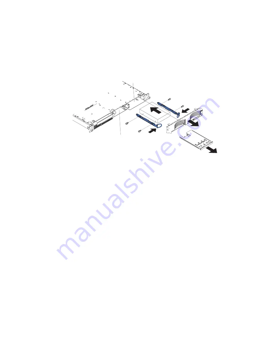
Drive bay 1

Drive bay 2


1.


Read


the


safety


information


that


begins


on


page


v,


and


“Installation


guidelines”


on


page


9.


2.


Turn


off


the


server


and


peripheral


devices,


and


disconnect


the


power


cords


and


all


external


cables.


3.


Remove


the


server


cover


(see


“Removing


the


cover


and


bezel”


on


page


10).


4.


Press


in


on


the


USB


option


tray


to


release


it


and


slide


the


tray


out


until


it


stops;


then,


press


the


retention


clip


at


the


bottom


rear


of


the


tray


and


remove


the


tray


from


the


server.


Press


on


the


bezel


retention


tabs


and


pull


the


bezel


directly


away


from


the


server.


Notes:


a.


If


you


have


only


one


non-hot-swap


hard


disk


drive,


install


it


in


the


right-hand


bay


(bay


2)


with


a


jumper


installed


in


the


cable-selection-enabled


position


of


the


jumper


block


on


the


rear


of


the


drive.


b.


If


you


have


two


drives


and


you


want


the


server


to


determine


the


master


drive


and


subordinate


drive


automatically,


install


jumpers


in


the


cable-selection-enabled


position


of


the


jumper


block


on


both


drives.


c.


If


you


want


to


assign


master


and


subordinate


drives


manually,


install


a


jumper


in


the


master


position


for


the


drive


in


bay


2


and


install


a


jumper


in


the


subordinate


position


for


the


drive


in


bay


1.

5.


Install


the


hard


disk


drive


in


the


drive


bay:


a.


Attach


the


rails


to


the


sides


of


the


drive


using


two


screws


for


each


rail.


b.


Slide


the


drive


into


the


bay


until


the


rail


latches


snap


into


place.


c.


Connect


the


signal


and


power


cables


to


the


rear


of


the


drive.


Keep


the


cables


clear


of


the


airflow


path


of


the


fan


behind


the


drive


bays.

6.


If


you


have


other


options


to


install,


install


them


now.


Otherwise,


go


to


“Completing


the


installation”


on


page


26.


20


eServer


326m


Type


7969:


Installation


Guide

Summary of Contents for 326m - eServer - 7969

Page 1: ... the reverse side of this page Start the server Did the server start correctly Yes No Install the server in the rack cabinet and cable the server and options then restart the server Was the server setup completed Use ServerGuide to install the operating system The server is ready to use Go to to register the server http www ibm com pc register Go to the Web for instructions http www ibm com suppor...

Page 2: ...ify that all optional devices you installed are on the ServerProven list at http www ibm com servers eserver serverproven compat us Is the server working correctly Is the problem solved Hardware or software problem View support telephone numbers at http www ibm com planetwide View information about IBM Support Line at or view support telephone numbers at http www ibm com services sl products http ...

Page 3: ...eServer 326m Type 7969 Installation Guide ...

Page 4: ...ge 55 and the Warranty and Support Information document on the IBM Eserver Documentation CD Second Edition November 2005 Copyright International Business Machines Corporation 2005 All rights reserved US Government Users Restricted Rights Use duplication or disclosure restricted by GSA ADP Schedule Contract with IBM Corp ...

Page 5: ...ver configuration 28 Chapter 3 Server controls LEDs and power 29 Front view 29 Rear view 31 Server power features 32 Turning on the server 32 Turning off the server 32 Chapter 4 Configuring the server 35 Using the ServerGuide Setup and Installation CD 35 Installing your operating system without using ServerGuide 36 Using the Configuration Setup Utility program 36 Using the baseboard management con...

Page 6: ...upport 54 Hardware service and support 54 Appendix B Notices 55 Edition notice 55 Trademarks 56 Important notes 56 Product recycling and disposal 57 Battery return program 58 Electronic emission notices 59 Federal Communications Commission FCC statement 59 Industry Canada Class A emission compliance statement 59 Australia and New Zealand Class A statement 59 United Kingdom telecommunications safet...

Page 7: ...talleert eerst de veiligheidsvoorschriften Ennen kuin asennat tämän tuotteen lue turvaohjeet kohdasta Safety Information Avant d installer ce produit lisez les consignes de sécurité Vor der Installation dieses Produkts die Sicherheitshinweise lesen Prima di installare questo prodotto leggere le Informazioni sulla Sicurezza Les sikkerhetsinformasjonen Safety Information før du installerer dette pro...

Page 8: ...Antes de instalar este producto lea la información de seguridad Läs säkerhetsinformationen innan du installerar den här produkten vi eServer 326m Type 7969 Installation Guide ...

Page 9: ...or reconfiguration of this product during an electrical storm v Connect all power cords to a properly wired and grounded electrical outlet v Connect to properly wired outlets any equipment that will be attached to this product v When possible use one hand only to connect or disconnect signal cables v Never turn on any equipment when there is evidence of fire water or structural damage v Disconnect...

Page 10: ... a lithium battery replace it only with the same module type made by the same manufacturer The battery contains lithium and can explode if not properly used handled or disposed of Do not v Throw or immerse into water v Heat to more than 100 C 212 F v Repair or disassemble Dispose of the battery as required by local ordinances or regulations viii eServer 326m Type 7969 Installation Guide ...

Page 11: ...the device v Use of controls or adjustments or performance of procedures other than those specified herein might result in hazardous radiation exposure DANGER Some laser products contain an embedded Class 3A or Class 3B laser diode Note the following Laser radiation when open Do not stare into the beam do not view directly with optical instruments and avoid direct exposure to the beam Class 1 Lase...

Page 12: ...tton on the device and the power switch on the power supply do not turn off the electrical current supplied to the device The device also might have more than one power cord To remove all electrical current from the device ensure that all power cords are disconnected from the power source 1 2 x eServer 326m Type 7969 Installation Guide ...

Page 13: ...ices 82 kg 180 lb WARNING Handling the cord on this product or cords associated with accessories sold with this product will expose you to lead a chemical known to the State of California to cause cancer and birth defects or other reproductive harm Wash hands after handling ADVERTENCIA El contacto con el cable de este producto o con cables de accesorios que se venden junto con este producto pueden...

Page 14: ...xii eServer 326m Type 7969 Installation Guide ...

Page 15: ...ion and technical updates complete the following steps Note Changes are made periodically to the IBM Web site The actual procedure might vary slightly from what is described in this document 1 Go to http www ibm com support 2 Under Search technical support type 7969 and click Search The server comes with an IBM ServerGuide Setup and Installation CD to help you configure the hardware install device...

Page 16: ...nts The IBM Eserver Documentation CD requires the following minimum hardware and software v Microsoft Windows NT 4 0 with Service Pack 3 or later Windows 2000 or Red Hat Linux v 100 MHz microprocessor v 32 MB of RAM v Adobe Acrobat Reader 3 0 or later or xpdf which comes with Linux operating systems Acrobat Reader software is included on the CD and you can install it when you run the Documentation...

Page 17: ...ments are opened in Acrobat Reader or xpdf To search all the documents type a word or word string in the Search field and click Search The documents in which the word or word string appears are listed in order of the most occurrences Click a document to view it and press Crtl F to use the Acrobat search function or Alt F to use the xpdf search function within the document Click Help for detailed i...

Page 18: ... step or situation Features and specifications The following information is a summary of the features and specifications of the server Depending on the server model some features might not be available or some specifications might not apply Racks are marked in vertical increments of 1 75 inches Each increment is referred to as a unit or U A 1 U high device is 1 75 inches tall 4 eServer 326m Type 7...

Page 19: ...al Serial Bus USB ports v One serial port v One video port Note The baseboard management controller is also known as the service processor Acoustical noise emissions v Declared sound power idling 6 5 bels v Declared sound power operating 6 5 bels Environment v Air temperature Server on 10 to 35 C 50 0 to 95 0 F Altitude 0 to 914 m 2998 7 ft Server on 10 to 32 C 50 0 to 89 6 F Altitude 914 m 2998 7...

Page 20: ... the component can be hot swapped which means that if the server and operating system support hot swap capability you can remove or install the component while the server is running Orange can also indicate touch points on hot swap components See the instructions for removing or installing a specific hot swap component for any additional procedures that you might have to perform before you remove ...

Page 21: ...rom your hardware Microprocessor heat sink Microprocessor Dual inline memory module DIMM System board Air baffle Microprocessor fans CD ROM drive assembly Hot swap hard disk drive SCSI backplane SCSI model only Power supply Hard disk drive fan air baffle Power cord module Hard disk drive Filler panel SCSI model only Bezel SCSI model only Microprocessor socket USB option tray Heat sink retention mo...

Page 22: ...8 eServer 326m Type 7969 Installation Guide ...

Page 23: ...ollowing precautions Make sure that you can stand safely without slipping Distribute the weight of the object equally between your feet Use a slow lifting force Never move suddenly or twist when you lift a heavy object To avoid straining the muscles in your back lift by standing or by pushing up with your leg muscles v Make sure that you have an adequate number of properly grounded electrical outl...

Page 24: ...ent Movement can cause static electricity to build up around you v The use of a grounding system is recommended For example wear an electrostatic discharge wrist strap if one is available v Handle the device carefully holding it by its edges or its frame v Do not touch solder joints pins or exposed circuitry v Do not leave the device where others can handle and damage it v While the device is stil...

Page 25: ...ve the USB option tray and the bezel only if you are installing a non hot swap hard disk drive It is not necessary if you are installing other options in the server 6 Press on the bezel retention tabs on the top right side and bottom of the server and pull the bezel directly away from the server Attention For proper cooling and airflow replace the cover before turning on the server Operating the s...

Page 26: ...n system resources By default the server starts boots devices in the following order system SCSI devices PCI express and PCI X devices then IDE and SATA devices Note To change the boot precedence for PCI and PCI X devices you must disable the devices through the Configuration Setup Utility program Start the Configuration Setup Utility program and select Startup from the main menu Then select Start...

Page 27: ...d connect it to the RAID adapter The following illustration shows the cable routing if you are installing the RAID adapter in PCI X slot 1 See the documentation that comes with the RAID adapter for any additional cabling instructions That documentation also provides information about installing the RAID software and configuring the RAID adapter Chapter 2 Installing options 13 ...

Page 28: ...the rear edge of the adapter to the Remote Supervisor Adapter II connector JMGT1 on the system board For details about installing a Remote Supervisor Adapter II see the documentation that comes with the adapter The following illustration shows the cable routing Remote Supervisor Adapter II connector JMGT1 Remote Supervisor Adapter II 20 pin planar cable with USB signals 14 eServer 326m Type 7969 I...

Page 29: ...ines on page 9 2 Turn off the server and peripheral devices and disconnect the power cords and all external cables 3 Remove the server cover see Removing the cover and bezel on page 10 4 Determine which PCI slot you will use for the adapter PCI X PCI Express slot 1 PCIE1 PCI Express slot 2 PCIE2 Chapter 2 Installing options 15 ...

Page 30: ... slot 1 Expansion slot clip adapter slot 2 Retention clip Alignment tab Attention Avoid touching the components and gold edge connectors on the adapter Make sure that the adapter is completely and correctly seated in the slot Incomplete insertion might cause damage to the system board or to the adapter 6 Remove the expansion slot cover from the slot 7 To gain access to PCI X slot 1 remove the PCI ...

Page 31: ...pter by its top edge or upper corners align it with the connector and press it firmly into the connector 10 Slide the expansion slot clip toward the server until it snaps into place to secure the adapter in the adapter slot 11 Connect any internal cables to the adapter See the instructions that come with the adapter for details Attention Make sure that the cables do not block the flow of air from ...

Page 32: ...t have indicator LEDs However you must attach the blue rails that come with the drive before installing it in the server v A non hot swap hard disk drive has a jumper block on the rear Install a jumper in the cable selection position of the jumper block For details see the notes under step 4 on page 20 and the documentation that comes with the drive v If you install only one hard disk drive for fa...

Page 33: ...from the applicable drive bay Note To ensure adequate system cooling do not operate the server for more than 2 minutes without either a hard disk drive or a filler panel installed in each bay 3 Install the new hard disk drive in the drive bay 4 Check the hard disk drive status LED and activity LED to verify that the drive is operating correctly 5 If you have other options to install install them n...

Page 34: ...rver Notes a If you have only one non hot swap hard disk drive install it in the right hand bay bay 2 with a jumper installed in the cable selection enabled position of the jumper block on the rear of the drive b If you have two drives and you want the server to determine the master drive and subordinate drive automatically install jumpers in the cable selection enabled position of the jumper bloc...

Page 35: ...all DIMMs in the following sequence DIMM pair DIMM slots 1 1 and 2 2 3 and 4 v To optimize system performance in a dual microprocessor configuration install DIMMs in the following sequence DIMM pair DIMM slots 1 1 and 2 2 7 and 8 3 3 and 4 4 5 and 6 v The server supports 512 MB 1 GB and 2 GB DIMMs The memory can be expanded to a maximum of 16 GB using PC3200 2 GB DIMMs See the ServerProven list at...

Page 36: ...el on page 10 Attention To avoid breaking the retaining clips or damaging the DIMM connectors open and close the clips gently 4 Open the retaining clip on each end of the DIMM connector 5 Touch the static protective package containing the DIMM to any unpainted metal surface on the server Then remove the DIMM from the package 6 Turn the DIMM so that the DIMM keys align correctly with the slot 7 Ins...

Page 37: ...ompleting the installation on page 26 Installing an additional microprocessor The following notes describe the type of microprocessor that the server supports and other information that you must consider when installing a microprocessor v For a list of microprocessors that the server supports see http www ibm com servers eserver serverproven compat us v The server comes with one microprocessor ins...

Page 38: ... the same cache size and have the same clock speed To install a microprocessor complete the following steps 1 Read the safety information that begins on page v and Installation guidelines on page 9 2 Turn off the server and peripheral devices and disconnect the power cords and all external cables 3 Remove the server cover see Removing the cover and bezel on page 10 then determine the socket where ...

Page 39: ... sink Doing so damages its heat conducting capability and exposes the new microprocessor to overheating a Remove the heat sink from its package and remove the cover from the bottom of the heat sink b Make sure that the thermal material is still on the bottom of the heat sink and position the heat sink on top of the microprocessor c Align the captive screws on the heat sink with the holes on the he...

Page 40: ...r engage the chassis correctly If all the tabs do not engage the chassis correctly it will be very difficult to remove the cover later 2 Position the cover on top of the server and slide it forward Press down on the cover latch The cover slides forward into position Make sure that the cover engages the tabs at the front and rear of the server 3 If you removed the bezel position the bezel directly ...

Page 41: ...ty program to update the server configuration For more information see Updating the server configuration on page 28 and the User s Guide on the IBM Eserver Documentation CD To attach non USB devices to the server use the cables that come with the devices and connect the cables to the appropriate ports on the server To attach a USB device to the server use the cable that comes with the device and c...

Page 42: ...tions have device drivers that you must install See the documentation that comes with each option for information about installing device drivers The server comes with at least one microprocessor If more than one microprocessor is installed the server can operate as an SMP server You might have to upgrade the operating system to support SMP For more information see the section about using the Serv...

Page 43: ...ciated SCSI hard disk drive is in use Power on LED When this LED is lit and not flashing it indicates that the server is turned on When this LED is flashing it indicates that the server is turned off and still connected to an ac power source When this LED is off it indicates that ac power is not present or the power supply or the LED itself has failed A power on LED is also on the rear of the serv...

Page 44: ... the rear of the server An LED near the failing component on the system board is also lit to help isolate the error USB connectors Connect a USB device to either of these connectors Important If a Remote Supervisor Adapter II is installed in the server the USB 1 connector is disabled Hard disk drive status LEDs On some server models each hot swap hard disk drive has a status LED If the status LED ...

Page 45: ... error has occurred An LED near the failing component on the system board is also lit to help isolate the error A system error LED is also on the front of the server Power on LED When this LED is lit and not flashing it indicates that the server is turned on When this LED is flashing it indicates that the server is turned off and still connected to an ac power source When this LED is off it indica...

Page 46: ...wer You can turn on the server and start the operating system by pressing the power control button The server can also be turned on in any of the following ways v If a power failure occurs while the server is turned on the server will restart automatically when power is restored v If an optional Remote Supervisor Adapter II is installed in the server the server can be turned on from the Remote Sup...

Page 47: ...ting system the server will be turned off automatically v You can press the power control button to start an orderly shutdown of the operating system and turn off the server if your operating system supports this feature v If the operating system stops functioning you can press and hold the power control button for more than 4 seconds to turn off the server v If an optional Remote Supervisor Adapt...

Page 48: ...34 eServer 326m Type 7969 Installation Guide ...

Page 49: ...rograms see Configuring your server in the User s Guide on the IBM Eserver Documentation CD Using the ServerGuide Setup and Installation CD The ServerGuide Setup and Installation CD provides state of the art programs to detect the server model and installed hardware options configure the server hardware provide device drivers and help you install your operating system For information about the sup...

Page 50: ...stallation instructions for your operating system Using the Configuration Setup Utility program The Configuration Setup Utility program is part of the BIOS You can use it to v Change interrupt request IRQ settings v Change the startup drive sequence v Configure serial port assignments v Resolve configuration conflicts v Set advanced hardware features v Set the date and time v Set passwords and sec...

Page 51: ...o the diskette drive or insert the firmware update CD into the CD drive 3 Turn on the server Note If the server does not start from the external USB diskette drive use the Configuration Setup Utility program to configure the external USB diskette drive as a startup device For information about the Configuration Setup Utility program see the User s Guide on the IBM Eserver Documentation CD Then sta...

Page 52: ...r v To update the firmware and BIOS codes for an optional ServeRAID controller you must use the IBM ServeRAID Support CD that comes with the controller v If you install a different type of RAID controller see the documentation that comes with the controller for information about viewing and changing SCSI settings for attached devices Using the LSI Logic Configuration Utility program To start the L...

Page 53: ... If ServeRAID Manager detects an unconfigured controller and ready drives the Configuration wizard starts In the Configuration wizard you can select express configuration or custom configuration Express configuration automatically configures the controller by grouping the first two physical drives in the ServeRAID Manager tree into an array and creating a RAID level 1 logical drive If you select c...

Page 54: ...e drives and physical drives When you click an object in the ServeRAID Manager tree information about that object appears in the right pane To display a list of available actions for an object click the object and click Actions Using the ServeRAID configuration programs A ServeRAID adapter enables you to configure multiple physical SCSI hard disk drives to operate as logical drives in a disk array...

Page 55: ...de for more information v Troubleshooting charts These charts list problem symptoms and steps to correct the problems See Troubleshooting charts on page 47 for more information v Diagnostic programs and error messages The server diagnostic programs are provided on the IBM Enhanced Diagnostics CD that comes with your server These programs test the major components of your server See the Hardware Ma...

Page 56: ...the pointing device then restart the server If the problem goes away replace the pointing device If the problem remains call for service 1 1 2 Microprocessor register test has failed Call for service 1 1 3 Complementary metal oxide semiconductor CMOS write read test has failed 1 1 4 BIOS read only memory ROM checksum has failed 1 2 1 Programmable Interval Timer test has failed 1 2 2 Direct memory ...

Page 57: ...server If the problem remains call for service 2 3 2 Screen memory test has failed Call for service 2 3 3 Screen retrace tests have failed 2 3 4 Search for video ROM has failed 2 4 1 Screen test indicates the screen is operable 3 1 1 Timer tick interrupt test has failed 3 1 2 Interval timer channel 2 test has failed 3 1 3 RAM test has failed above address hex 0FFFF 3 1 4 Time of Day clock test has...

Page 58: ...ations the 3 3 3 beep code might sound during POST followed by a blank monitor screen If this occurs and the Boot Diagnostic Screen or QuickBoot Mode feature on the Start Options menu of the Configuration Setup Utility program is enabled its default setting you must restart the server three times to force the BIOS to reset the configuration to the default configuration the memory connectors enable...

Page 59: ...ur server and that they are installed correctly 301 303 Keyboard and keyboard controller Make sure that the keyboard cable is connected and that nothing is resting on the keyboard keys 962 Parallel port configuration error Run the Configuration Setup Utility program and make sure that the parallel port setting is correct 1162 Serial port configuration conflict Run the Configuration Setup Utility p...

Page 60: ...cannot be installed v Make sure that there are no duplicate SCSI IDs or IRQ assignments v Make sure that the hard disk drive is connected correctly The operating system installation program continuously loops Make more space available on the hard disk The ServerGuide program will not start the operating system CD Make sure that the operating system CD is supported by the ServerGuide program See th...

Page 61: ...the server bypasses the diskette drive If there is a diskette in the drive make sure that v The diskette drive cables are correctly and securely connected v The diskette drive is enabled in the Configuration Setup Utility program v The diskette is good and not damaged Try another diskette if you have one v The diskette contains the necessary files to start the server v Your software program is wor...

Page 62: ...ille If there is no airflow the fan is not working This can cause the server to overheat and shut down v The SCSI bus and devices are configured correctly and the last external device in each SCSI chain is terminated correctly If the problem remains call for service Keyboard mouse or pointing device problems Symptom Suggested action All or some keys on the keyboard do not work v Make sure that the...

Page 63: ...ice Monitor problems Some IBM monitors have their own self tests If you suspect a problem with your monitor see the information that comes with the monitor for instructions for testing and adjusting the monitor If you cannot diagnose the problem call for service Symptom Suggested action The screen is blank Make sure that v The server power cord is connected to the server and a working electrical o...

Page 64: ...te the BIOS code with the correct language If the problem remains call for service Option problems Symptom Suggested action An IBM option that was just installed does not work Make sure that v The option is designed for the server See the Server Support flowchart for information about obtaining ServerProven compatibility information from the World Wide Web v You followed the installation instructi...

Page 65: ... Make sure that v Each port is assigned a unique address in the Configuration Setup Utility program and none of the serial ports are disabled v The serial port adapter if you installed one is seated correctly If the problem remains call for service A serial device does not work Make sure that v The device is compatible with the server v The serial port is enabled and is assigned a unique address v...

Page 66: ...ymptom Suggested action A USB device does not work Make sure that v The correct USB device driver is installed v Your operating system supports USB devices If the problem remains call for service 52 eServer 326m Type 7969 Installation Guide ...

Page 67: ...bmit a request for information You can solve many problems without outside assistance by following the troubleshooting procedures that IBM provides in the online help or in the documentation that is provided with your IBM product The documentation that comes with Eserver and IntelliStation systems also describes the diagnostic tests that you can perform Most Eserver and IntelliStation systems oper...

Page 68: ...ons and appliances For information about which products are supported by Support Line in your country or region see http www ibm com services sl products For more information about Support Line and other IBM services see http www ibm com services or see http www ibm com planetwide for support telephone numbers In the U S and Canada call 1 800 IBM SERV 1 800 426 7378 Hardware service and support Yo...

Page 69: ...NTY OF ANY KIND EITHER EXPRESS OR IMPLIED INCLUDING BUT NOT LIMITED TO THE IMPLIED WARRANTIES OF NON INFRINGEMENT MERCHANTABILITY OR FITNESS FOR A PARTICULAR PURPOSE Some states do not allow disclaimer of express or implied warranties in certain transactions therefore this statement may not apply to you This information could include technical inaccuracies or typographical errors Changes are perio...

Page 70: ...e United States other countries or both UNIX is a registered trademark of The Open Group in the United States and other countries Java and all Java based trademarks and logos are trademarks of Sun Microsystems Inc in the United States other countries or both Adaptec and HostRAID are trademarks of Adaptec Inc in the United States other countries or both Linux is a trademark of Linus Torvalds in the...

Page 71: ...or a particular purpose These products are offered and warranted solely by third parties IBM makes no representations or warranties with respect to non IBM products Support if any for the non IBM products is provided by the third party not IBM Some software may differ from its retail version if available and may not include user manuals or all program functionality Product recycling and disposal T...

Page 72: ...ntain a sealed lead acid nickel cadmium nickel metal hydride lithium or lithium ion battery Consult your user manual or service manual for specific battery information The battery must be recycled or disposed of properly Recycling facilities may not be available in your area For information on disposal of batteries outside the United States go to http www ibm com ibm environment products batteryre...

Page 73: ... cause harmful interference and 2 this device must accept any interference received including interference that may cause undesired operation Industry Canada Class A emission compliance statement This Class A digital apparatus complies with Canadian ICES 003 Avis de conformité à la réglementation d Industrie Canada Cet appareil numérique de la classe A est conforme à la norme NMB 003 du Canada Aus...

Page 74: ...easures Taiwanese Class A warning statement Chinese Class A warning statement Japanese Voluntary Control Council for Interference VCCI statement Power cords For your safety IBM provides a power cord with a grounded attachment plug to use with this IBM product To avoid electrical shock always use the power cord and plug with a properly grounded outlet IBM power cords used in the United States and C...

Page 75: ... Republic of Czech Republic Dahomey Djibouti Egypt Equatorial Guinea Eritrea Estonia Ethiopia Finland France French Guyana French Polynesia Germany Greece Guadeloupe Guinea Guinea Bissau Hungary Iceland Indonesia Iran Kazakhstan Kyrgyzstan Laos People s Democratic Republic of Latvia Lebanon Lithuania Luxembourg Macedonia former Yugoslav Republic of Madagascar Mali Martinique Mauritania Mauritius M...

Page 76: ...Taiwan United States of America Venezuela 24P6858 Korea Democratic People s Republic of Korea Republic of 34G0232 Japan 36L8880 Argentina Paraguay Uruguay 49P2078 India 49P2110 Brazil 6952300 Antigua and Barbuda Aruba Bahamas Barbados Belize Bermuda Bolivia Caicos Islands Canada Cayman Islands Colombia Costa Rica Cuba Dominican Republic Ecuador El Salvador Guam Guatemala Haiti Honduras Jamaica Mex...

Page 77: ... 35 connector Ethernet 31 local area network LAN 31 power cord 31 serial 31 USB 30 31 video 31 controls front 29 operator information panel 30 cover installing 26 removing 11 D danger statements 3 diskette drive problems 47 USB 28 documentation CD 2 dual in line memory module DIMM installing 21 E electrical input specifications 5 electronic emission Class A notice 59 environment air temperature 5 ...

Page 78: ...tallation 36 notes important 3 56 notices electronic emission 59 notices continued FCC Class A 59 notices and statements 3 O online publications 1 operating system installation 36 operator information panel 30 option problems 50 P PCI Express x8 expansion slot 12 PCI X buses 12 PCI X expansion slot 12 pointing device problems 48 POST error messages 45 power control button 29 cord connector 31 LED ...

Page 79: ...r 30 system error LED 30 31 system locator LED 30 T trademarks 56 transmit receive activity LEDs 31 troubleshooting chart 47 turning off the server 32 turning on the server 32 U United States electronic emission Class A notice 59 United States FCC Class A notice 59 Universal Serial Bus USB problems 52 updating the firmware 37 USB connectors 30 31 requirements 27 utility program baseboard managemen...

Page 80: ...66 eServer 326m Type 7969 Installation Guide ...

Page 81: ......

Page 82: ... Part Number 40K0994 Printed in USA 1P P N 40K0994 ...

Reviews: