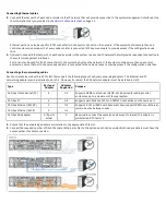
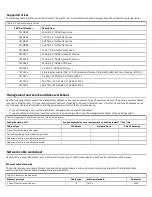
background image

Ethernet port type

Cable type

Minimum standard

Connector

10 Gbps onboard Ethernet ports

TP

Cat 6 (up to 55 m), Cat 6a or Cat 7 (up to

100 m) at 10 Gbps, or Cat 5e at 1 Gbps

RJ45

25 Gbps Ethernet host interface adapter (must be ordered)

Optical

OM3 (up to 70 m) OM4 (up to 100 m)

LC

Table 4: Ethernet cable standards(continued)

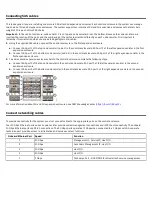
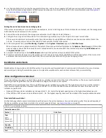
Onboard Ethernet ports

In the control enclosure, Ethernet port 1 of each node canister is connected to an enabled port on your Ethernet switch or router. Ethernet

port 1 is used for accessing the management GUI, for accessing the service assistant GUI for the node canister, and for iSCSI host

attachment. You can also attach an Ethernet cable from Ethernet port 2 on the node to canister your Ethernet network. Port 2 can be used

for the management GUI and for iSCSI host attachment. Ethernet ports 3 and 4 are for iSCSI attachment only.

The ports on the upper node canister (canister 1) are

numbered from right to left.

The ports on the lower node canister (canister 2) are

numbered from left to right.

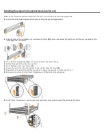
Use the following table to record the connections to the onboard Ethernet ports of each node canister in the control enclosure.

Control Enclosure S/N:

Node Canister 1

Ethernet Port 4

Ethernet Port 3

Ethernet Port 2

Ethernet Port 1

Technician Port

Switch

None

Port

None

Speed: 1 or 10 Gbps

1 Gbps

Node Canister 2

Ethernet Port 1

Ethernet Port 2

Ethernet Port 3

Ethernet Port 4

Technician Port

Switch

None

Port

None

Speed: 1 or 10 Gbps

1 Gbps

Table 5: Onboard Ethernet port worksheet

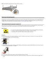
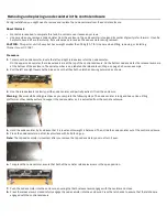
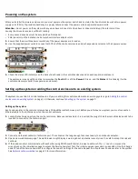
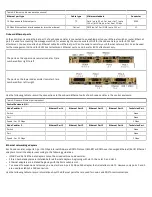
Ethernet networking adapters

Each node canister supports 2-port 25 Gbps internet Wide-area RDMA Protocol (iWARP) or RDMA over Converged Ethernet (RoCE) Ethernet

adapters. Install the adapters according to the following guidelines.
• iWARP and RoCE Ethernet adapters cannot be mixed within a node canister.
• Fibre Channel adapters are installed before Ethernet adapters, beginning with slot 1, then slot 2, and slot 3.
• Ethernet adapters are installed beginning with the first available slot.
• To connect to expansion enclosures, you must order a 4-port 12 Gbps SAS adapter that is installed in slot 3. However, only ports 1 and 3

are used to establish a SAS connection

Use the following table to record information about the Ethernet ports that are used for node-node RDMA communications.

Summary of Contents for 2076-824

Page 1: ...you start the installation process ensure that the following items are available Philips screw driver Box knife Flat blade screw driver optional Three Ethernet cables The control enclosure and the fol...

Page 2: ...carefully cut along the lower fold line of the sides and remove them 7 Carefully cut the raised section of the foam packing away from the rear of the enclosure 8 Carefully cut open the bag that cover...

Page 3: ...the inside 2 of the rack cabinet 3 Close the front hinge bracket 3 to secure the rail to the rack cabinet flange 4 Extend the length of the side rail as needed 5 Close the hinge at the rear of the rai...

Page 4: ...continuing to power the enclosure if the other fails About this task You must follow recommended procedures for handling electrostatic discharge ESD sensitive devices No tools are required to complet...

Page 5: ...6 on page 5 shows an example 2 Pull the left and right levers by the blue ends so that they both unlatch and swing outwards as shown 3 Use the release levels to slowly pull the node canister and part...

Page 6: ...y for more than 10 minutes during servicing IBM FlashCore Modules are not interchangeable with the flash modules that are used in IBM FlashSystem 900 storage enclosures Procedure 1 To remove the drive...

Page 7: ...rst expansion enclosure 2 To add a second expansion enclosure chain to the control enclosure complete the following steps a Connect SAS port 3 of the top node canister in the control enclosure to SAS...

Page 8: ...guration node fails Connecting other networking cables Each control enclosure has three PCI slots that support the following types of optional networking adapters The Ethernet and FC networking adapte...

Page 9: ...em The system can contain 1 4 control enclosures If you are adding this control enclosure to an existing system go to Adding the control enclosure to an existing system on page 10 Otherwise continue t...

Page 10: ...pplication outside of the system If the two control enclosures lose communication with each other the quorum disk prevents both I O groups from going offline Installation worksheets Worksheets can hel...

Page 11: ...is bound to Ethernet port 2 Both IPv4 and IPv6 addresses can be used Specify the type of installation and the serial number S N of the control enclosure If you are installing a new system installatio...

Page 12: ...able to record the connections to the onboard Ethernet ports of each node canister in the control enclosure Control Enclosure S N Node Canister 1 Ethernet Port 4 Ethernet Port 3 Ethernet Port 2 Ethern...

Page 13: ...2 Port 5 Port 6 Port 7 Port 8 Port 9 Port 10 Switch Port Speed 25 or 10 Gbps Cable type Node IP Subnet mask Gateway VLAN ID Table 6 Ethernet adapter port connection worksheet Fibre Channel connection...

Page 14: ...tion number at the end of each caution notice or each danger notice In the following examples the numbers C001 and D002 are the identi cation numbers CAUTION A caution notice indicates the presence of...

Page 15: ...ons and to initiate menu actions that can also be done through mouse actions You can go to the system online documentation from the keyboard by using the keyboard shortcuts for your browser or screen...

Page 16: ...y IBM under terms of the IBM Customer Agreement IBM International Program License Agreement or any equivalent agreement between us The performance data discussed herein is presented as derived under s...

Page 17: ...elevision broadcasts Warning This equipment is compliant with Class A of CISPR 32 In a residential environment this equipment may cause radio interference Germany Notice Deutschsprachiger EU Hinweis H...

Page 18: ...er t erf llt die Schutzanforderungen nach EN 55024 und EN 55032 Klasse A Japan Electronics and Information Technology Industries Association JEITA Notice This statement applies to products less than o...

Page 19: ...erference in which case the user will be required to correct the interference at his own expense Properly shielded and grounded cables and connectors must be used in order to meet FCC emission limits...

Page 20: ...all subsequent modi cations until otherwise indicated in new editions Copyright International Business Machines Corporation 2020 US Government Users Restricted Rights Use duplication or disclosure res...

Reviews: