background image

FWA7304 Series User’s Manual 


6

Chapter 4  Console Mode Information 

FWA7304 supports output information via Console in BIOS level. 
 

Prepare a computer as client loaded with an existing OS such Windows XP. 
Connect client computer and FWA7304 with NULL Modem cable. 
Follow the steps below to configure the Windows Hyper Terminal application setting: 


1.  For executing the Hyper Terminal, issue command “hypertrm”. 
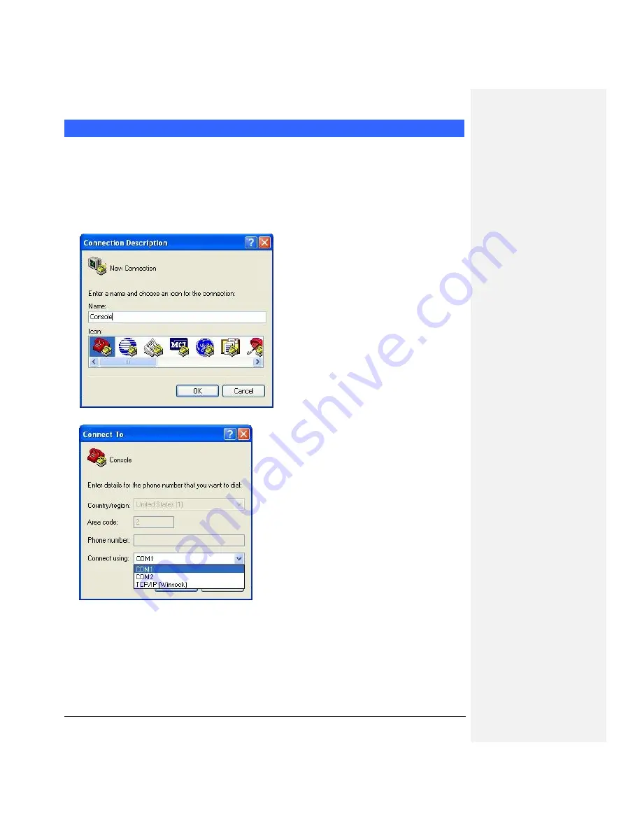
2.  Customize your name for the new connection. 


3.  Choose the COM port on the client computer for the connection. 


4.  Please make the port settings to Baud rate 19200, Parity None, Data bits 8, Stop bits 1 

Summary of Contents for FWA7304 Series

Page 1: ...FWA7304 Series Network Appliance User s Manual Version 1 0...

Page 2: ...em Specification 4 Chapter 3 Hardware Configuration 5 Chapter 4 Console Mode Information 6 Chapter 5 Opening the chassis 8 Chapter 6 Removing and Installing CompactFlash Card 9 Chapter 7 Installing th...

Page 3: ...should the Lithium battery cell used to power the real time clock be allowed to be shorted The battery cell may heat up under these conditions and present a burn hazard WARNING 1 CAUTION DANGER OF EXP...

Page 4: ...Server Network Management Applications Load balancing Quality of Service Remote Access Service The FWA network appliance product line covers the spectrum from offering platforms designed for SOHO SMB...

Page 5: ...h Bridge Expansion slots 32bit 33MHz Mini PCI slot x 1 Ethernet Realtek RTL8100C Fast Ethernet controllers x 4 10 100 Base T Front I O USB 2 0 ports x 2 Power LED x 1 Status LED GPO x 2 Alarm LED GPO...

Page 6: ...ader to clear the CMOS contents JBAT1 Setting Function Pin 1 2 Short Closed Normal Pin 2 3 Short Closed Clear CMOS JP3 HDD UDMA Selection JP4 Setting Function Pin 1 2 Short BIOS Detect Pin 1 3 Short U...

Page 7: ...XP Connect client computer and FWA7304 with NULL Modem cable Follow the steps below to configure the Windows Hyper Terminal application setting 1 For executing the Hyper Terminal issue command hypertr...

Page 8: ...ries User s Manual 7 5 Power up the FWA7304 and the screen will display the following information 6 Press Tab key to enter BIOS setup screen in Console mode Press Del key to enter BIOS setup screen in...

Page 9: ...s Manual 8 Chapter 5 Open the chassis 1 Fig 5 1 Loosen the four screws of the chassis on the back to remove the top lead Fig 5 2 The top lead Fig 5 2 can be removed from the base stand Fig 5 3 2 Fig...

Page 10: ...FWA7304 Series User s Manual 9 Chapter 6 Removing and Installing CompactFlash Card 1 Fig 6 1 Compact Flash Card Fig 6 2 Insert Compact Flash Card into the CF interface...

Page 11: ...FWA7304 Series User s Manual 10 Chapter 7 Installing Mini PCI Card Fig 7 1 Mini PCI card Fig 7 2 Install the Mini PCI card...

Page 12: ...8 1 Fasten the four screws to lock HDD and bracket together Fig 8 2 Fasten the four stands off to lock IB798 Blue portion for long stands off Red portion for short stands off Fig 8 3 Connect IDE cabl...

Page 13: ...FWA7304 Series User s Manual 12 Chapter 9 System Architecture The following block diagram illustrates a basic design reference of IB798 a highly integrated system solution...

Reviews: