background image


25                                                                     

MAN-85 – USA


         Assume to use the engine with  Z=11 teeth sprocket and that during the preliminary 

tests a Z=72 teeth axle sprocket has been used.  


  From  Table  1  with  Z=11  as  engine  sprocket  and  Z=72  on  the  axle  sprocket,  a 

ratio of 6.55  is found. 


  Make a few laps on the track and, record the max RPMs achieved  by the engine. 

Assume that we read 12.000 RPMs. 


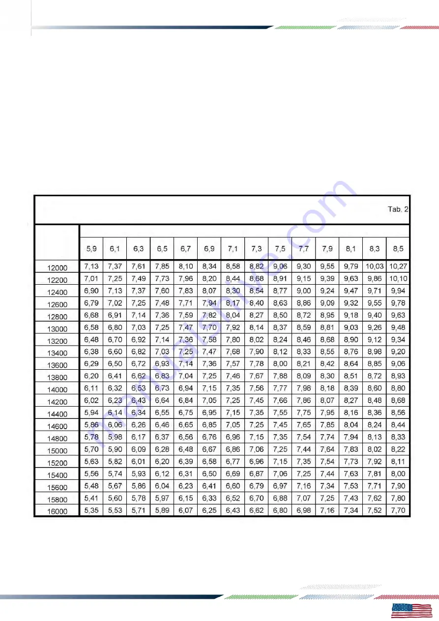
  From  the  Table  2  to  achieve  a  max.  RPM  14.500  (operating  limit  for  the  MINI 

SWIFT engine) a sprocket ratio of 7.85 should be used (having used, during the 

tests, a sprocket ratio of 6.55 and having achieved 12.000 RPMs). 


  From  Table  1,  to  achieve  a  sprocket  ratio  of  7.85,  a  Z=86  teeth  axle  sprocket 

should be used. 


Sprocket ratio to achieve max. 14.500 RPM 

Sprocket ratio 

Engine max. 

RPM during 

tests 

Summary of Contents for MINI SWIFT 60CC - USA

Page 1: ...MAN 85 USA Installation MANUAL MINI SWIFT 60CC USA ...

Page 2: ...ical connections 3 8 Electrical connections on the engine 3 9 Install the intake silencer 3 10 Install the exhaust 4 Gasoline and Oil 5 Tillotson HW 31A carburettor adjustment 6 Starting and stopping the engine 7 Engine break in 8 Inlet silencer 9 Recommendations on the exhaust system 10 Centrifugal clutch 11 Instructions for the disassembly assembly of the clutch 12 Battery 13 Use of the battery ...

Page 3: ...on roller bearings The ignition includes a 2 pole stator rotor an H T coil a starter relay and complete wiring harness The spark is generated also without a battery it is therefore possibile in case of emergency to start the engine with an external starter unit The engine has an integrated electric starter By pushing the green start button the starter activates a Bendix type gear which engages the...

Page 4: ...tic dry centrifugal Operational limits Max RPM 1 14 500 RPM ATTENTION Never exceed the above limits no obligation of IAME exists in case the above limits are exceeded 1 CONTENTS OF PACKING Each engine is supplied with the accessories under shown EXHAUST Quantity Exhaust silencer spring 2 Exhaust manifold 1 Exhaust muffler 1 INDUCTION Tillotson carburettor 1 Intake silencer 1 Intake silencer suppor...

Page 5: ... MAN 85 USA ACCESSORIES COPERCHIO FRIZIONE SILENZIATORE DI ASPIRAZIONE EXHAUST GROUP ELECTRIC WIRES BATTERY SUPPORTS CLUTCH COVER INTAKE SILENCER NGK SPARK PLUG TILLOTSON HW 31A CARBURETTOR INTAKE GROUP ...

Page 6: ... see fig The number normally includes a letter followed by 4 digits Other numbers stamped on the crankcase or other surfaces of the motor refer to various manufacturing processes and do not identify the engine NOTE In case of need for spare parts and when contacting the IAME Support Centers please always refer to the Motor Identification Number and to the motor model ...

Page 7: ...is it is at care of the assembler to follow these instructions The final customer in this case can skip this section and can start reading from section 4 Whenever the engine or a component is disassembled it is necessary to always follow the under shown instructions for proper reassembly 3 1 INSTALLATION SKETCH OF THE ENGINE ON THE CHASSIS ...

Page 8: ...ER 3 2 2 INSTALL SPRINGS ON THE EXHAUST HEADER SEE FIG 1 MAKE SURE THAT THE EXHAUST GASKET IS IN SEAT AND INSTALL THE EXHAUST HEADER SEE FIG 2 NOTE ON THE BABY VERSION THE EXHAUST HEADER IS NOT REQUIRED 3 2 3 INSTALL THE 2 WASHERS 6mm SUGGESTION PUT THE ENGINE IN HORIZONTAL POSITION USE A SCREWDRIVER IF NECESSARY AND INSTALL THE WASHERS IN SEAT 3 2 4 INSTALL THE 2 NUTS SEE FIG 3 TORQUE AT 9 11 Nm ...

Page 9: ...CREW MUST PROTRUDE FROM THE PLATE FOR 16 19mm SEE FIG 4 AND DRAW 4 ALLEN SCREWS M8 TORQUE AT 22 24 Nm 190 210 in lb 6mm ALLEN WRENCH 3 4 INSTALL THE CARBURETTOR REMOVE THE PLASTIC CAP KEEPING 1 CARBURETTOR GASKET ON THE ENGINE INSTALL SEE FIG 10 N 2 THERMICAL SPACER 15mm 11 5mm N 2 CARBURETTOR GASKET CARBURETTOR N 2 COLOMN NUTS 12 POINT WRENCH 5mm CONNECT BY APPROPRIATE PIPE THE INTAKE PRESSURE MA...

Page 10: ...MPS UNTIL THE CHAIN IS INSTALLED AND PROPERLY ALIGNED 3 5 2 CHECK THE ALIGNMENT OF THE ENGINE SPROCKET AND THE AXLE SPROCKET SEE FIG 13 3 5 3 INSTALL THE CHAIN PITCH 7 775 SEE FIG 14 3 5 4 MOVE THE ENGINE ON THE RAILS AND OPTIMIZE THE CHAIN TENSION ATTENTION THE PLAY OF THE CHAIN MUST BE APPR 15mm MEASURED IN THE SHOWN POINT SEE FIG 15 3 5 5 TORQUE THE CLAMPS SCREWS Fig 12 Fig 13 Fig 14 Fig 15 15m...

Page 11: ...ORQUE THE 3 SCREWS AT 8 10 Nm 70 90 In lb 5 mm ALLEN WRENCH ATTENTION MAKE SURE THAT THE COPPER GROUND CABLE ALWAYS CONNECTS THE COIL WITH THE ENGINE AN INADEQUATE GROUNDING COULD DAMAGE THE IGNITION BEYOND REPAIR THE POSITION OF THE H T COIL HAS BEEN CHOSEN TO BE AS FAR AS POSSIBLE FROM THE EXHAUST AS THE EXCESSIVE HEAT COULD DAMAGE THE COIL BEYOND REPAIR Fig 16 A Fig 16 B ...

Page 12: ...G 17 N 2 SCREWS M6x10 TORQUE SCREWS AT 8 10 Nm 70 90 in lb 12 POINT WRENCH 10 mm 3 7 1 POSITION THE SUPPORT ON THE CHASSIS REAR RAIL SEE FIG 18 3 7 2 FIX THE CLAMPS SEE FIG 19 N 2 SCREWS M6x25 TORQUE SCREWS AT 8 10 Nm 70 90 in lb 5 mm ALLEN WRENCH 3 7 3 INSERT THE STRAP INTO THE SUPPORT SLOTS SEE FIG 20 Fig 18 Fig 19 Fig 20 Fig 17 ...

Page 13: ...22 NOTE THE 2 CABLES PROVIDED WITH 10mm TERMINALS CAN BE INVERTED ON THE STARTER RELAY WITHOUT CAUSING ANY MALFUNCTION PROBLEMS ALSO THE 2 CABLES WITH 6 3mm TERMINALS CAN BE INVERTED 3 8 ELECTRICAL CONNECTIONS ON THE ENGINE REFER TO THE ATTACHED ELECTRICAL SCHEMATIC UNSCREW THE M6 SCREW ON THE STARTER AND CONNECT THE GROUND CABLE TO THE ENGINE SEE FIG 23 TORQUE SCREW AT 8 10 Nm 70 90 in lb 5 mm AL...

Page 14: ... 3 8 3 CONNECT THE SECOND TERMINAL OF THE IGNITION STATOR TO THE MALE CONNECTOR OF THE HARNESS SEE FIG 26 3 8 4 FIX THE HARNESS WITH PLASTIC CLAMPS ALONG THE CHASSIS REAR RAIL SEE FIG 27 3 8 5 FIX THE BATTERY AND HARNESS TERMINALS BY MEANS OF THE STRAP SEE FIG 28 Fig 25 Fig 26 Fig 27 Fig 28 ...

Page 15: ...SS GET IN TOUCH WITH THE GROUND OR WITH ROTATING PARTS AS IT COULD BE DAMAGED BEYOND REPAIR 3 8 7 FIX THE REMAINING HARNESS ALONG THE RAIL BRAKE SIDE WITH PLASTIC CLAMPS SEE FIG 30 3 8 8 REMOVE THE STEERING WHEEL AND POSITION THE PUSH BUTTON SUPPORT BRACKET ON THE HUB SEE FIG 31 3 8 9 ASSEMBLE THE PUSH BUTTONS INTO THE SUPPORT BRACKET SEE FIG 32 Fig 29 Fig 27 Fig 30 Fig 31 Fig 32 ...

Page 16: ...PLIED WITH THE ENGINE TORQUE AT 20 26 Nm 175 230 in lb POSITION THE SPARK PLUG CAP ON THE SPARK PLUG Fig 33 Fig 34 Fig 35 Caution should be taken when installing the spark plug Always clean and inspect the spark plug threads before installation Always apply anti seize compound grease or oil NEVER INSTALL THE SPARK PLUG WITHOUT SOME LUBRICATION You should be able to freely turn the plug into the he...

Page 17: ... IS NOT PLUGGED TIGHTEN THE FIXING CLAMP ON THE CARB AND FIX THE FILTER BY MEANS OF THE PROPER CLAMP ON THE CHASSIS RAIL SEE FIG 37 38 3 10 INSTALL THE EXHAUST SYSTEM INSTALL THE EXHAUST MUFFLER ON THE FITTING AND SECURE IT WITH THE 2 SPRINGS SEE FIG 39 NOTE ON THE BABY VERSION THE MUFFLER IS DIRECTLY POSITIONED ON THE CYLINDER WITHOUT ANY INTERMEDIATE FITTING ENGINE IS READY TO BE STARTED Fig 37 ...

Page 18: ...ead Our experience dictates use of oils such as WLADOIL K 2T KART RACING OIL SHELL ADVANCE RACING M ELF HTX 909 Once the fuel tank is filled make sure that the gasoline reaches the carburetor before starting the engine Never use the electric starter to suck the gasoline as this would discharge the battery SUGGESTION Disconnect the plastic tube on the carb pump and the vent tube on the tank and pre...

Page 19: ...pen T O 45 Based on various factors as altitude ambient temperature etc It might be necessary to reset the carburettor to optimize the performance of the engine ATTENTION Never lean too much as lean mixture will overheat engine and cause seizure Do not force H or L closed It may damage the precision machined orifice and render the carb unserviceable The adjustment of screw must be performed with w...

Page 20: ...ame RPM for a long time 4 Increase the speed for approx 5 minutes at max speed with throttle wide open and making the engine rich at half straight cover with the hand for an instant the holes on the air filter keeping the throttle wide open ATTENTION Once the break in is over and the engine is cold check the torque of the exhaust header nuts as during the break in the nuts tend to become loose ref...

Page 21: ...mage the chain and sprocket Check the clutch Every 5 hours of use When metallic noises are heard inside the clutch If the kart dragging speed exceeds 5000 RPMs Every time the clutch has overheated presence of smoke or smell of burning To check the clutch you must remove the clutch cover and the clutch drum Replace the clutch Whenever the thickness of the friction material see drawing is lower than...

Page 22: ...itting P N 10271 3 Remove nut 1 nut M10 12 Point wrench 17 mm 4 Remove the external washer the drum with roller cage the internal washer 5 Remove the special tool from the head and using the clutch wrench remove the M16x1 nut and the cone safety washer ATTENTION Turn clockwise as nut has left thread Clutch wrench P N 10270 24 mm socket 6 Apply clutch puller on clutch and remove clutch from the cra...

Page 23: ...he M16 x1 nut using the clutch wrench ATTENTION turn counterclockwise as nut has left thread Clutch wrench P N 10270 12 Point wrench 24 mm Torque at 40 50 Nm 350 440 in lb 5 Install the internal washer ATTENTION install washer with bevel towards internal part of engine Clean the roller cage and grease it before installing it on the crankshaft 6 Install the clutch drum and the external washer ATTEN...

Page 24: ...ry at least once every 6 months Never let the battery tension dropping under 8V as whenever it drops under this limit the battery cannot be used any longer and it has to be replaced Never put the battery in contact with solvents gasolines oils plastifiers or rags containing such elements The external case of the battery could be damaged Never press or bend or overheat by welding the battery termin...

Page 25: ...ver INSTRUCTIONS FOR USE 1 Connect the red plug of the battery charger to the terminal red of the battery and the blue plug to the terminal black 2 Plug in the battery charger to a 220 V 50 hz current tap 3 When charging the red led of the battery charger is lightened When the battery is fully charged the red led is off 4 Recharging time of a competely discharged battery approx 7 8 hrs ATTENTION D...

Page 26: ...rate the same final look which can be also achieved with a hot or cold spark plug See table an excessively warm spark plug shows the symptoms listed aside ATTENTION Always use a warmer than standard spark plug with cold or rainy climates Extremely clear color porous look and calcification of the electrodes and of the internal insulation Irregularities in the ignition preignition and detonation wit...

Page 27: ...rformance without abusing the engine follow the under shown recommendations The engines are supplied with a 11 teeth sprocket pitch 7 775 mm Table 1 shows the various ratios between the sprocket on the axle and the engine sprocket given the different axle sprockets Sprocket ratio Teeth n Engine sprocket Sprocket ratio Teeth n Engine sprocket Teeth n Axle sprocket 11 Teeth n Axle sprocket 11 72 6 5...

Page 28: ...k and record the max RPMs achieved by the engine Assume that we read 12 000 RPMs From the Table 2 to achieve a max RPM 14 500 operating limit for the MINI SWIFT engine a sprocket ratio of 7 85 should be used having used during the tests a sprocket ratio of 6 55 and having achieved 12 000 RPMs From Table 1 to achieve a sprocket ratio of 7 85 a Z 86 teeth axle sprocket should be used Sprocket ratio ...

Page 29: ...y Check status and charge Cables and connectors Check status and connections Engine mount and clamps Check torques After use Battery Disconnect Chain Check status and oil chain Engine External cleaning Every 5 10 hours Bendix assembly Remove cover see fig and clean internally Exhaust muffler Remove muffler end clean Inlet silencer Open clean Engine head Open clean Clutch Open and check status of p...

Page 30: ...ad H T coil grounding Check grounding Wet or damaged spark plug Replace Malfunction on feed system Check status and connections on fuel pipe Replace membranes and gaskets on fuel pump Rough idle Bad carb adjustment L screw Check carb adjustm see sect 5 Drop in engine performance Bad compression Check piston status Bad carb adjustment Check carb adjustm see sect 5 Insufficient gas fuel flow Ckeck g...

Page 31: ...be preserved as follows Disconnect the battery and charge it periodically see sect 12 Disconnect carburetor and clean it Seal with tape the engine inlet and exhaust The external of the engine must be cleaned Spray with protective oil the steel parts subject to oxidation Keep the engine in a dry ambient ...

Page 32: ...29 MAN 85 USA 29 ...

Reviews: