
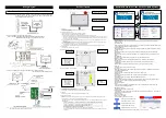

Wiring Diagram
The standard cable (5m) is connected to the TB-02 main body. Connect each controller cable to this standard cable for use.
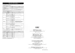
(1) Position controller ERC2, ERC3, RCP6S, RCM-P6
□
C, ACON, PCON, SCON, DCON, MCON, MSCON,
RACON, RPCON, RCON, ASEP, PSEP, DSEP, MSEP, AMEC, PMEC, REC,
ELECYLINDER (CB-TB1-C002 is used.)
(2) Program controller XSEL-J/JX (CB-TB1-XJ005 is used.)
Program controller XSEL-K/KX/KT/KET/P/PX/PCT/Q/QX/QCT/R/RX/RXD/S/SX/SXD
/RA/RAX/RAXD/SA/SAX/SAXD, TT/TTA (CB-TB1-X002 is used.)
(3) Program controller MSEL-PC/PCF/PG/PGF/PCX/PGX, SSEL, ASEL, PSEL, RSEL
(CB-TB1-X002 and CB-SEL-SJS002 are used.)
(Note) For other wiring except connection with Touch Panel Teaching Pendant TB-02, refer to the first
step guide or instruction manual of each controller.
Each Part Name
Front surface (Standard specification/(Deadman switch specification)
1) Stop
switch
Press this to stop operation.
To cancel the stop status, turn this switch in the arrow direction.
2) Display and touch panel unit
The screen consists of a TFT Color LCD Type and a touch panel.
Various settings that have been edited or taught are displayed.
To operate the screen, use a finger or the touch pen to touch desired parts of the touch panel.
*1 In a use of the LCD display for a long time, the brightness may drop. To maximize the life of the LCD display, set the
turn-off time in the environment setting so that it can be automatically turned off. In addition, when the LCD display is
not in use, remove it from the controller.
*2 This touch panel is of analog resistance membrane type, so do not touch two or more locations on the screen at the
same time.
If two or more locations are touched at the same time, the centers of all touched locations may respond and trigger
multiple operations.
*3 When operating the touch panel, do not apply a force exceeding 0.5 N.
If any greater force is applied, the touch panel may be damaged.
*4 The life of touch panel is approx. 1 million touches at the same location. (Assuming a use environment of 25°C)
3) Standard
cable
The cable of 5m is connected to the main body.
Rear surface (Standard specification)
Rear surface (Deadman switch specification)
4) Secure Digital Memory Card Slot Cover
There is the SD memory card insertion unit inside this cover.
Insert and remove the SD memory card by referring to the instruction manual.
5) Touch
pen
This touch pen is used to touch the touch-panel operation display screen.
6) Wall-mounting
hook
unit
This hook is used to mount the touch panel on a wall. The hook is available to hang with an M8 hex socket head cap
screw.
7) Deadman switch unit (This is not provided in standard specification.)
The dead man switch has three conditions corresponding to three levels. The meaning of ON/OFF in each condition is
explained below.
Level 1
Switch OFF
The hand is off the switch, or the switch is pressed with a very small force.
Level 2
Switch ON
The switch is pressed with an appropriate force.
Level 3
Switch OFF
The switch is pressed with a strong force.
When the switch is ON, the servo can be turned ON.
When the switch is OFF, the drive source is cut off and the servo remains OFF.
Even when the switch is OFF, operation is still possible in modes where the servo need not be ON (such as in the
edit mode).
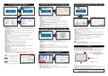
Operation Menu for Position Controller (CON System)
Screen when position controller starts
Screen at CON System Controller Startup
Menu 1 screen
Menu 2 screen
Position Edit Guide
Explains the position data input and trial operation according to the real position data editing screen in
interactive mode.
I/O Control Guide
Explains the positioning action by I/O control under the "PIO pattern:0" condition in interactive mode as the
user operates the equipment according to instructions.
Simple Program Set
Sets the data necessary for a desired action from the sample program and performs trial operation in order
in interactive mode.
Monitor
Displays the actuator status, I/O signal status, maintenance information and production information.
Edit Position
Sets the position, velocity, acceleration, deceleration, etc. to operate actuators. It is available to manual
mode.
Edit Parameter
Adjusts parameters when adjusting the system and using the attendant functions.
SD Memory Card
Reads and saves the position data, parameters and alarm list. Updates the TB-02 software.
Servo Monitor
Displays the real operating status of actuator with waveforms. It is possible to record data.
Trial Operation
Performs manual operation and I/O test by specifying jog, inching and numerical values.
Alarm List
Displays an alarm and the time of its occurrence.
Information
Shows the software version, network information, production information, maintenance information and
connectable model information.
Trouble Shooting
Displays the alarm contents and remedial measure when an alarm occurs.
Change Axis
Selects an axis to be displayed when the controller can be connected with two or more axes.
TP Op. Mode
Prohibits/permits PIO operation and validates/invalidates safety velocity.
Environment Set
Conduct settings for display language, Touch tone, DimDispTime, Data input warning, Disp Axis Name,
Ripple compensation, password, display, time and Startup screen setting.
Controller Reset
Restarts the controller.
Others
Conduct parameter initialization and change axis No., load cell calibration, load cell inactivation, I/O
customize, encoder cable length setting.
Maintenance Parts List
Displays the maintenance parts information.
Simple Program
It is possible to set the movement between positions, timer and repeat of specified times. This screen is
used for manual continuous operation.
Off-board Tuning
Sets the off-board tuning.
Pulse Train Control Mode
Sets for performing the pulse train control.
:
Returns to the preceding screen.
: Returns to the "Menu 1" screen.
: Displays the "Glossary" screen.
: Displays the "Monitor" screen.
: Displays the "Change Axis" screen.
(Note) For details of operation, refer to the screen display or instruction manual.
5) Touch pen
4) Secure Digital
Memory Card Slot
Cover (Inside,
secure digital
memory card inlet)
5) Touch pen
6)
Wall-mounting
hook unit
Caution: Turn the controller power OFF before connecting or disconnecting the touch panel teaching pendant TB-02.
1) Stop switch (Gray or Red)
2) Display and touch panel unit
3) Standard cable (5m)
4) Secure Digital
Memory Card Slot
Cover (Inside,
secure digital
memory card inlet)
6)
Wall-mounting
hook unit
7)
Deadman
switch unit


