—
60
—
AP-
16
00T-
PMCL
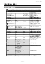
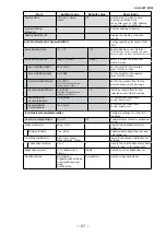
Item
Setting range
Default value
Description
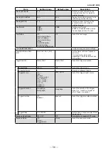
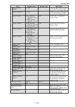
ColorTransformationRGB
Mode
Off,
sRGB,
AdobeRGB,
User Custom
Off
Set the detailed mode when RGB is
selected for the color space.
ColorMatrixValueSelector
ColorMatrixR-R,
ColorMatrixR-G,
ColorMatrixR-B,
ColorMatrixG-R,
ColorMatrixG-G,
ColorMatrixG-B,
ColorMatrixB-R,
ColorMatrixB-G,
ColorMatrixB-B
–
Select the ColorMatrix setting
component.
ColorMatrixValue
-2.0 to 2.0
–
Set the Color Matrix value.
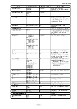
g) DigitalI/OControl
Configure settings for digital input/
output.
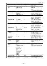
LineSelector
Line1-TTLOut1,
Line2-OptOut1,
Line5-OptIn1,
Line6-OptIn2,
Line7-CC1,
NAND0In1,
NAND0In2,
NAND1In1,
NAND1In2
Line2-OptOut1
Select the input/output to configure.
LineMode
Input,
Output
Output
Display the input/output status
(whether it is input or output).
LineInverter
True, False
False
Enable/disable polarity inversion for
the selected input signal or output
signal.
LineStatus
True, False
False
Display the status of the input signal
or output signal (True: High, False:
Low).
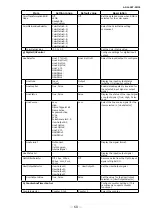
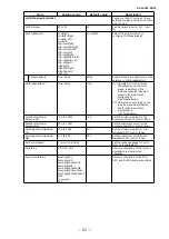
LineSource
Low,
High,
FrameTriggerWait,
FrameActive,
ExposureActive,
FVAL,
LVAL,
PulseGenerator0-3,
UserOutput0-3,
Line5OptIn1,
Line6OptIn2,
Line7-CC1,
NAND0Out,
NAND1Out
Low
Select the line source signal for the
item selected in [LineSelector].
LineFormat
NoConnect,
TTL,
OptoCoupled,
InternalSignal
–
Display the signal format.
LineStatus All
–
–
Display the input/output signal
status.
OptInFilterSelector
Off, 10µs, 100µs,
500µs, 1ms, 5ms,
10ms
Off
Remove noise from the OptIn input
signal of Digital I/O.
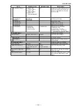
UserOutputSelector
UserOutput0,
UserOutput1,
UserOutput2,
UserOutput3
0: UserOutput0
Set the UserOutput signal.
UserOutputValue
True, False
False
Set the value for the UserOutput
selected in [UserOutputSelector].
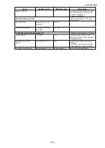
h) CounterAndTimerControl
Configure counter settings. (This
camera only supports counter
functions.)
CounterSelector
Counter 0 to 2
Counter 0
Select the counter.

