background image

4  |  Learn more about i3 products at www.i3-learning.com 

Step 1: Environment Check  

Before setting up and installing the projector and Light Curtain Touch module, ensure 
that the interactive cable work for the installation location of the mount in advance.  

Note:


Make sure the projector is installed under the following conditions: 
- The projected image is a rectangular shape without any distortion. 
- The projector is tilted at an angle no more than +/-3 degrees vertically and horizontal 
in relation to the screen. 
- When using the interactive function, install the projected image within reach. 
- Do no install the projector or screen in a location subject to direct sunlight. If the 
projector or the screen is subject to direct sunlight, the interactive function may not 
operate correctly. 

A.


Light Curtain Touch installation Information 

Before installing the Light Curtain Touch module, the projection surface must meet 
the following conditions/criteria: 

1.


The screen surface is a flat, smooth unwrapped surface with no unevenness of 
more than 5mm. The surface can either be a flat wall or a whiteboard. For 
details on how to check surface flatness see page 8. 

2.


The surface must allow for the Light Curtain Touch module to be fixed with 
screws. 
 

If the projection surface meets the criteria above the projector and Light Curtain 
Touch module can then be installed in one of the following ways 

1.


Mount the projector to the wall and the Light Curtain Touch module to the 
whiteboard. 

2.


Mount the projector and Light Curtain Touch module to the wall. 


Summary of Contents for 3303WI

Page 1: ......

Page 2: ... Check 4 Step 2 Installing the Light Curtain Touch module 7 Step 3 Install Utility Software 9 Step 4 Initial Setup 10 Step 5 Operation Mode 11 Step 6 Laser Beam Alignment 12 Step 7 Touch Area Setting 15 Step 8 Calibration 17 Step 9 Touch Sensitivity 18 Step 10 Trouble shooting Viewer 19 Trouble shooting 20 ...

Page 3: ...ouch module which is attached to the whiteboard To operate normally IR camera should face the projection image area on the wall Remove any obstacle in between IR camera and Light Curtain Touch module Do not place other infrared communication devices lighting equipments or residential heating equipments etc nearby Only use the interactive cable from accessory kit L side connector should plug into L...

Page 4: ...f the projector or the screen is subject to direct sunlight the interactive function may not operate correctly A Light Curtain Touch installation Information Before installing the Light Curtain Touch module the projection surface must meet the following conditions criteria 1 The screen surface is a flat smooth unwrapped surface with no unevenness of more than 5mm The surface can either be a flat w...

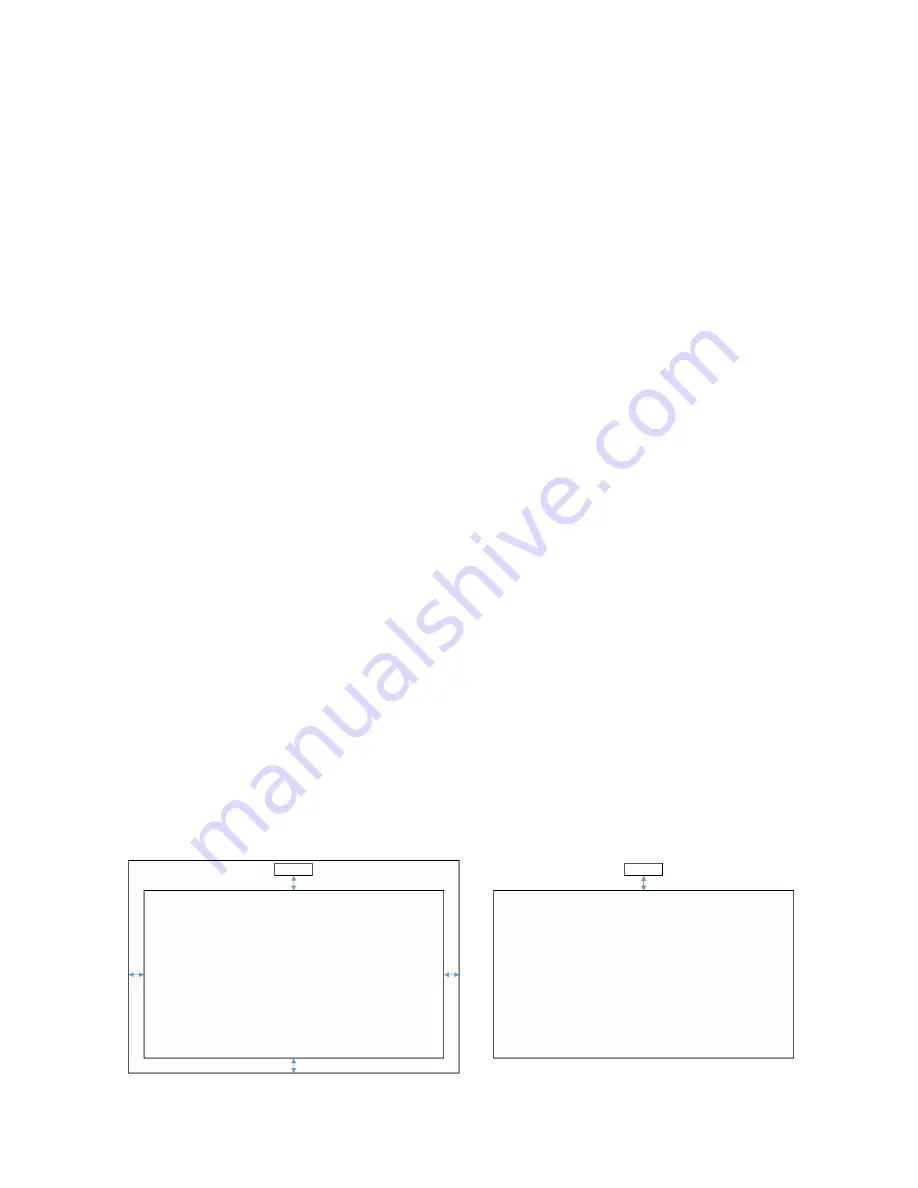
Page 5: ...f 10mm as shown in diagram on the previous page For standard aspect ratio 4 3 16 10 and 16 9 gap 2 10cm From the top of image area a gap must be kept 2 10cm away from the bottom of LCT module For suggested whiteboard frame design height 3mm keep 10mm bezel at left right bottom of image area For regular whiteboard ex aluminum frame height 3mm keep 50mm bezel at left right bottom of image area For u...

Page 6: ...tion surface flatness Criteria overall whiteboard flatness 5mm flatness requirement is 3mm at Light Curtain Touch module mounting area Equipment leveling instrument 1 2 1 5m and thickness gauge Split projection area into 16 segments equally as below chart Place leveling instrument on whiteboard Fra White board IR CAMERA 3mm 3mm White board IR CAMERA NG OK Point1 Point2 Point3 Point4 Point5 Point6 ...

Page 7: ... Curtain Touch module Keep away distance to image area for standard aspect ratio 4 3 16 10 and 16 9 5 5 13 5cm from bottom of base plate 2 10cm from bottom of Light Curtain Touch module 2 1 For short term demonstration 2 1 1 Clean surface with isopropyl rubbing alcohol wipe gently let dry 2 1 2 Adhere double sided tape enclosed in accessory box onto base plate then paste onto the whiteboard or wal...

Page 8: ... term use Use screws to fix base plate onto whiteboard Drill tip ΦO 2 3mm Screw type M3x6L Screw head ΦO 5 5mm thickness 2 5mm 3 Fix curtain module with wall plate by screws 4 Plug power cord to Light Curtain Touch module Note L side connector must plug into Light Curtain Touch module ...

Page 9: ...nt to check your system condition System requirement Operating system Microsoft Windows XP SP3 Windows 7 32bit 64bit Windows 8 Windows 8 1 NET Framework 4 0 must be installed Mac OS X 10 7 10 10 CPU Intel Core i3 or above Memory 2GB or more B Install software utility from CDROM Utility icon indicator as below Finger Stylus Active Pen Disconnected ...

Page 10: ...10 Learn more about i3 products at www i3 learning com Step 4 Initial Setup For first time setup follow Installation Guide to complete installation procedure ...

Page 11: ... Windows 7 and Windows 8 operating system support multi point touch control Users can select default Touch Mode for multi point touch Switch to Pen Mode while using light pen IR pen For Windows XP and Mac OS X only single point touch is available ...

Page 12: ...he Red LED will blink continuously LED indicator Mode Blue LED Red LED Description IR Laser mode Solid IR laser ON Visible light mode Solid Blinking Visible light ON IR Laser OFF touch disabled Error Solid Error of LD module occurred 2 Connect PC and Projector via USB cable 3 Rotate the black and grey knobs clockwisely until they stop ...

Page 13: ...ter clockwisely until both beams are symmetrically at the same level 5 Rotate black knob counter clockwise move beams downwards until they hit whiteboard frame 6 Check the beam height with alignment sticker The beams should be located within grey zone ...

Page 14: ...n to switch back to IR mode The Blue LED will stay solid LED indicator Mode Blue LED Red LED Description IR Laser mode Solid IR laser ON Visible light mode Solid Blinking Visible light ON IR Laser OFF touch disabled Error Always ON Error of LD module occurred 8 Put top cover back ...

Page 15: ... Note Quit all software application Reduce ambient light Do not obstruct or shake lens during Touch Area Setting Check if projection image is clear If not adjust focus to sharpen the image If fail message pops up switch to Manual Touch Area Setting B Select Manual Touch Area Setting ...

Page 16: ... which is reversed from projection image For example P1 is lower right corner P2 is lower left corner and so on B 2 Touch Area Boundary Fine tuning Step 1 Click on P1 use mouse to drag P1 to upper left corner Align adjustable green zone with projected white frame Step 2 Adjust P2 to P4 accordingly adjustable green zone should completely overlaps the projected white frame Step 3 Finally check again...

Page 17: ...again Close all software application Reduce ambient light Do not obstruct or shake lens during calibration Check if projection image is clear If not adjust focus to sharpen the image If the Auto Calibration fail message still pops up on screen switch to Manual Calibration B Select Manual Calibration Note Manual Calibration is suggested for better accuracy ...

Page 18: ... 9 Touch Sensitivity When touch function is unresponsive or writing is intermittent You can adjust the sensitivity by adjusting Touch Sensitivity level Default 4 Max 10 most sensitive Min 0 least sensitive Note Touch Sensitivity is not adjustable under Pen Mode ...

Page 19: ...es may interfere with touch performance The troubleshooting viewer shows real time images for debugging purposes Any light interference is marked in green If green obstacles appear within image area remove to secure proper interactivity Note Interactive function is disabled under trouble shooting viewer click to exit ...

Page 20: ...SB device A 1 Unplug re plug in the USB cable and check again 2 Switch to another USB port and check again 3 Restart your computer and check again 4 Go to Power Options in Control Panel check USB selective suspend settings status in USB settings under Advance Settings Switch to Disabled 5 Go to official website of the laptop PC manufacturer and update USB driver to latest version 6 Use the USB cab...

Page 21: ...start your computer and check again 5 Go to Power Options in Control Panel check USB selective suspend settings status in USB settings under Advance Settings Switch to Disabled 6 Go to official website of the laptop PC manufacturer and update USB driver to latest version 7 Go to official website of the laptop PC manufacturer and update BIOS driver to latest version 8 Use the USB cable included wit...

Page 22: ...A Please perform Calibration and Touch Area setting during first installation If projector or whiteboard is moved Touch Area Setting and Calibration should be performed again When Laptop PC resolution is changed calibrate again For better accuracy please do Manual Calibration If an overlarge offset is observed please perform Manual Calibration and see Step 8 Calibration for troubleshooting Q6 What...

Page 23: ...g Calibration d Check if projection image is clear If not adjust focus to sharpen the image e If the Auto Touch Area Setting failed or Auto Calibration failed message pops up on screen again please switch to Manual Mode to do Touch Area Setting and Calibration 2 Please check Projector Lamp Power Mode selection Lower lamp brightness ECO mode may affect both Auto Touch Area Setting and Auto Calibrat...

Page 24: ... for detailed procedures check if Manual Touch Area boundary is located properly Q9 What to do when projection area corner is insensitive or intermittent lines are observed A 1 Adjust the level of Touch Sensitivity to enhance sensitivity see Step 9 Touch Sensitivity for trouble shooting 2 If Touch function remains insensitive please check the optical port condition If dust or particles are observe...

Page 25: ...Wi PLUS USER MANUAL 25 2 Select Smaller 100 Default and click Apply ...

Page 26: ...ulti touch 10 touch points Win 7 and Win8 compliant Multi touch Min Distance 40mm Hover Z depth Default hover height is 5 5mm Working Projection Image Size 70 100 XGA co operate with TR0 25 UST projector 80 100 WXGA co operate with TR0 25 UST projector 80 100 1080P co operate with TR0 25 UST projector 120 140 16 6 ultra wide co operate with TR0 25 UST projector Display mode Support Ceiling mode on...

Page 27: ...tain Touch Module 1 2 Screw M2 6x6 to fix LCT module 2 3 Screw M3x6 to fix base plate 2 4 Interactive cable 1 5 Alignment sticker 2 6 LCT module base plate 1 7 Double sided tape for base plate 1 8 5m USB A to mini USB B cable 1 9 Passive Pen 2 10 CD for User Manual and Utility Software 1 ...

Page 28: ...28 Learn more about i3 products at www i3 learning com ...

Reviews: