

5
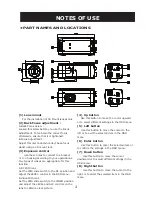
(9) Tripod Stand
Application for mounting the camera onto
the camera holder. Effective for general camera
tripods.
(10) RJ-45 Terminal
Remote control for the OSD menu and B.C.G
function
(11) Video Output Terminal
BNC :Used to give out the video signal.
Connected to the video input terminal of a
monitor, switcher, etc. (to be terminated with
75 ohm impedance)
(12) Y/C Output Terminal :
For Y/C video signal output. Commercially
available S-Video output cables can be
employed. (Y=Luminance, 1Vp-p, 75 ohms.
C=Chrominance, 0.3Vp-p<burst>, 75 ohms.)
(13) DC12V/AC24V Power Connector
Connect this connector to the respe-
ctive power source.(DC12V/AC24V model
only)
WARNING: This apparatus must be EARTHED.
(14) AC90V~260V
Connect this connector to the respe-
ctive power source.(AC90~260V model
only)
WARNING: This apparatus must be EARTHED.
NOTES OF USE
•CONNECTIONS
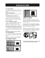
RJ-45 connector
•
BCG Control
When the D/N MODE is set into B.C.G mode,
the camera will change between COLOUR mode
and B/W mode manually according to the RJ-45
B.C.G commands.
A.When the PIN 4 (C/L) terminal is connected
with GND, the camera will change to permanent
colour. Releasing C/L and GND, the camera will
follow AUTO light lux level settings.
B.When the pin 6 (B/W) terminal is connected
with GND, the camera will change to permanent
B/W. Releasing B/W and GND, the camera will
follow AUTO light lux level settings.
*NOTE: SW1 symbolises electronic switching (PIR)
or manual switching (Voltage free contact).


