background image

< 4.4 > QD OSD Operation 

© (f) 

Quad Display Control 

o

o

o

o

o

o

o

d)

 VCR SEQ

 ffi

 B

 a

 E

 a 

1—Selup—1 V A < > 

© 

© 

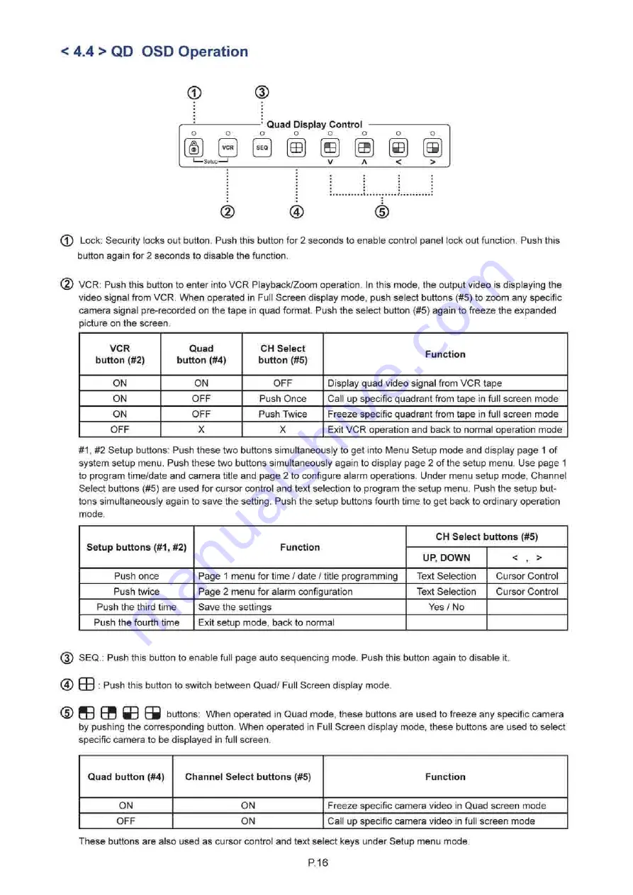
(T) Lock: Security locks out button. Push this button for 2 seconds to enable control panel lock out function. Push this 

button again for 2 seconds to disable the function. 

(2) VCR: Push this button to enter into VCR Playback/Zoom operation. In this mode, the output video is displaying the 

video signal from VCR. When operated in Full Screen display mode, push select buttons (#5) to zoom any specific 

camera signal pre-recorded on the tape in quad format. Push the select button (#5) again to freeze the expanded 
picture on the screen. 

VCR 

button (#2) 

Quad 

button (#4) 

CH Select 

button (#5) 

Function 

ON 

ON 

OFF 

Display quad video signal from VCR tape 

ON 

OFF 

Push Once 

Call up specific quadrant from tape in full screen mode 

ON 

OFF 

Push Twice 

Freeze specific quadrant from tape in full screen mode 

OFF 

Exit VCR operation and back to normal operation

 mode 

#1, #2 Setup buttons: Push these two buttons simultaneously to get into Menu Setup mode and display page 1 of 

system setup menu. Push these two buttons simultaneously again to display page 2 of the setup menu. Use page 1 

to program time/date and camera title and page 2 to configure alarm operations. Under menu setup mode, Channel 

Select buttons (#5) are used for cursor control and text selection to program the setup menu. Push the setup but­
tons simultaneously again to save the setting. Push the setup buttons fourth time to get back to ordinary operation 
mode. 

Setup buttons (#1, #2) 

Function 

CH Select buttons (#5) 

Setup buttons (#1, #2) 

Function 

UP, DOWN 

< , > 

Push once 

Page 1 menu for time / date / title programming 

Text Selection 

Cursor Control 

Push twice 

Page 2 menu for alarm configuration 

Text Selection 

Cursor Control 

Push the third time 

Save the settings 

Yes / No 

Push the fourth time 

Exit setup mode, back to normal 

(5) SEQ.: Push this button to enable full page auto sequencing mode. Push this button again to disable it. 

(4)  Q J : Push this button to switch between Quad/ Full Screen display mode. 

buttons: When operated in Quad mode, these buttons are used to freeze any specific camera 

by pushing the corresponding button. When operated in Full Screen display mode, these buttons are used to select 

specific camera to be displayed in full screen. 

Quad button (#4) 

Channel Select buttons (#5) 

Function 

ON 

ON 

Freeze specific camera video in Quad screen mode 

OFF 

ON 

Call up specific camera video in full screen mode 

These buttons are also used as cursor control and text select keys under Setup menu mode. 

P.16 

Summary of Contents for NPQW819

Page 1: ...ckmount screen technology User Manual 19 Widescreen LCD 1440 x 900 NPQW819 8U Quad Display Options DC power F C StREACH T E j I i Tech Company LLC C DN RA N f TOLL FREE 888 483 2418 EMAIL info iTechLC...

Page 2: ...n the chassis Opening it yourself could damage the equipment and invalidate its warranty If any part of the equipment becomes damaged or stops functioning have it checked by qualified service personne...

Page 3: ...ications P 4 2 2 On screen Display Operation OSD P 6 Part 3 Options 3 1 48V 24V or 12VDC power P 7 Part 4 Quad Display Connection Operation 4 1 QD Connection P8 4 2 QD ALARM Connection Operation P 9 4...

Page 4: ...X 1 Power cord X 1 1 2 Structure Diagram Front view 0 LCD panel LCD OSD membrane Quad display control membrane Power adapter basket Rear view RS 232 VCR in Video IN 1 r 4 o o o Alarm I O VCR out Opti...

Page 5: ...LO CO o o o o o o o o CD CXJ 0 CD 00 LO CO 410 5 rC CO 480 rC CO Side View 72 5 UNIT mm 1mm 0 03937 inch Bottom View 480 QQQQ D O O O O o o 440 Model Product Dimension W x D x H Packing Dimension W x...

Page 6: ...1 3 Installation Step Mount the display panel with M6 screw set M6 screw x 8 pcs required Left right side M6 screw sets are not provided Step O Fix the LCD into the rack P 3...

Page 7: ...ght Type LED MTBF hrs 30 000 Video Connectivity Analog VGA Analog 0 7Vp p Power Supply Range Auto sensing 100 to 240VAC 50 60Hz Power Consumption Screen display ON 25W or less Power Consumption Power...

Page 8: ...5 1 x 20 8 inch Net Weight 9 5 kgs 20 9 lbs Gross Weight 12 5 kgs 27 5 lbs VGA Input PC Signal 1440 x900 x60Hz 1280 x 1024 x 60 75Hz 1280 x960 x60Hz 1280x760x60 75Hz 1152 x864 x75Hz 1024x768x60 70 75H...

Page 9: ...Temp Red Green Blue Image Brightness Contrast Color Temp Red Green Blue User 1 1 Image Brightness Contrast Color Temp Red Green Blue User Image Brightness Contrast Color Temp Red Green Blue User J I...

Page 10: ...ng Input voltage 12 Volt 24 Volt 48 Volt Input range 9 18V 18 36V 36 75V Input current No load 50 mA 50 mA 50 mA Full load 4950 mA 2450 mA 1220 mA Output rating Output voltage 12 Volt 12 Volt 12 Volt...

Page 11: ...se switches toggle be tween 75Q and Hi Z impedance Incorrect termination will degrade the quality of the video signal All video inputs not looped through to another device the corresponding switches n...

Page 12: ...RD and STOP switch to the alarm output NC and NO contacts will allow you to use an ordinary VCR to record for longer period of time Combined with alarm sensor detection the VCR will record only when a...

Page 13: ...ng the Alarm Reset In contact pin 5 of the female type 9 pin D sub connector 8 to GND 2 The Alarm Duration time elapses 3 If the device is operated under Security Lock ON mode Push Lock button for 2 s...

Page 14: ...4 3 QD Remote Control Connection Operation ALARM I O vcr RS 232 Cable Wire P 11...

Page 15: ...e device to the computer A RS 232 port only uses pin 1 2 and 3 for control signal transmission 2 A terminal or computer can be connected to the male type 9 pin D sub connector on the real panel from i...

Page 16: ...than 4 seconds to clear the alarm 3 Setup menu is switched ON by sending VCR DVR and Lock button codes together 4 Text Select and Cursor Control functions can be performed only under menu Setup mode 2...

Page 17: ...tus of the alarm operations of the unit BYTE1 BYTE 2 START STOP START STOP BYTE 1 Status code for normal operation modes b7 b6 b5 b4 b3 b2 b1 bO LOCK VCR SEQU QUAD CH4 CH3 CH2 CH1 Channel Select 1110...

Page 18: ...f each channel The digit 1 means alarm event is detected and 0 means no alarm event is detected b7 b4 Sensor Activated Alarm b3 bO Video Loss Alarm b7 b6 b5 b4 b3 b2 b1 bO Ch 4 CH3 CH2 CH1 CH4 CH3 CH2...

Page 19: ...program time date and camera title and page 2 to configure alarm operations Under menu setup mode Channel Select buttons 5 are used for cursor control and text selection to program the setup menu Pus...

Page 20: ...characters may be entered for each video channel The available alphanumeric characters are 0 1 2 3 4 5 6 7 8 9 A B C D X Y Z space 1 2 DWELL Time setup The Dwell time menu permits setting the dwell t...

Page 21: ...d type of sensor a blinking message will display In this case the buzzer will be activated when you exit the setup operation 2 2 Alarm Sensitivity Alarm sensitivity can be programmed to different exte...

Page 22: ...mera input 6 The Full Screen Display Mode 6 1 Push Quad button 4 to OFF to enter Full screen display mode Under this mode you may call up any spe cific channel in full screen by simply pushing the cor...

Page 23: ...iption Model Number QD NTSC j QD PAL Number of Color 16 7 M j 16 7 M Imaging System NTSC PAL Resolution 1024x525 j 1024x625 Refresh Rate 60 50 Video Input Camera Input 1 0 Vpp 75 Ohm x 4 Video Input V...

Page 24: ...I TECH COMPANY i Tech C o m p a n y LLC TOLL FREE 888 483 2418 EMAIL info iTechLCD com WEB www iTechLCD com...

Reviews: