background image

3

1. GENERAL INFORMATION

The I-Gard SIGMA-MD monitor relay is a combination neutral grounding resistor (NGR) monitor and ground fault 
relay. In distribution systems employing high resistance grounding, the SIGMA-MD monitor relay protects against 
ground faults and abnormal resistance values of the neutral grounding resistor (NGR).

The SIGMA-MD monitor relay is specifically designed for a variety of system voltages and a neutral grounding 
resistor (NGR) limiting the maximum NGR current to the relay’s set let through current.

The SIGMA-MD monitor relay is designed to be used with a TxA type zero sequence current sensor, an NGRS-XX 
resistor sensor and an NGR sized to limit ground fault current to that stated in the installation’s specifications.

The let-through current measured by the zero sequence current sensor will be the vector sum of any leakage 
currents or charging currents normally in the system and any ground fault currents that may be present.

Hazard of Electrical Shock, Burn or Explosion

All installation, servicing and testing referred to in this manual must be 

performed by qualified personnel. All power should be disconnected 

prior to removing covers or enclosures and where live conductors 

may otherwise be exposed.

Failure to observe these precautions may result in death or severe 

personal injury and damage to equipment. Before placing an 

intentional ground fault on the power system, check that a fault does 

not already exist. Any test ground fault equipment must be rated for 

full system voltage and be fused for protection.

DANGER

IMPORTANT

Each SIGMA-MD monitor relay and its auxiliary parts, is carefully inspected before being packed in specially 

designed cartons. Any unit received should be examined immediately upon receipt. If damage or indication of rough 

handling is apparent, a claim should be filed with the transport company immediately. I-Gard should be notified 

promptly if replacements for damaged goods are necessary. If units received are not to be installed immediately 

they should be stored in their original containers in an area free of dust and moisture.

Summary of Contents for SIGMA-MD

Page 1: ...C EG42EM Instruction Manual December 2018 Previously C 455EM GROUND FAULT RELAY NEUTRAL GROUNDING RESISTOR SIGMA MD...

Page 2: ...s 10 6 1 Start Up and Reset Indications 10 6 2 Power on Led Green 11 6 3 Ground Fault Led Red 11 6 4 NGR Fault Led Red 11 6 5 Zone Ground Led Red 12 7 Self Test 12 8 Relay Settings 13 8 1 Trip Relay O...

Page 3: ...omer service and technical leadership We build on this foundation by investing in developing new products in electrical safety education including EFC scholarship program by actively participating in...

Page 4: ...present Hazard of Electrical Shock Burn or Explosion All installation servicing and testing referred to in this manual must be performed by qualified personnel All power should be disconnected prior...

Page 5: ...minal value When the ZSCS current is below 1 of the NGR let through current setting the SIGMA MD monitor relay simply monitors the NGR resistance for continuity i e whether the NGR is open or presents...

Page 6: ...fast response is necessary as failure of the NGR implies that there is limited ground fault protection on the system It also ensures fast tripping when a transformer is energized and the resistor is...

Page 7: ...necting the NGRS from the SIGMA MD monitor relay the R terminal of the NGRS should be disconnected BEFORE the Ground connection is removed from the G terminal of the SIGMA MD monitor relay The procedu...

Page 8: ...e trip relay terminals the auxiliary fault relay terminals the external reset test and the G F meter terminals If door panel mounted or remote test and or reset controls are required connect momentary...

Page 9: ...MD MONITOR RELAY AND NGR The SIGMA MD monitor relay has settings for the let through current ground fault trip current level and ground fault time delay These settings may be specified in the installa...

Page 10: ...r if the SIGMA MD processor fails this normally closed relay will open The contacts will close when the power LED turns on and remain closed as long as the relay is operating correctly All relays are...

Page 11: ...et flashing The trip relay auxiliary fault relays and associated LED will remain as such indefinitely regardless of whether a fault is present on the system and until the conditions which caused the t...

Page 12: ...l be ON when the SIGMA MD monitor relay has detected and qualified a ground fault The RED GND FAULT LED will remain ON until the SIGMA MD monitor relay is manually reset even if the NGR fault conditio...

Page 13: ...GMA MD monitor relay and no voltage applied to system transformer s primary winding Alternatively the system transformer s primary winding may be powered with the system transformer secondary isolated...

Page 14: ...en control voltage is applied to the SIGMA MD monitor relay and the system is operating normally The trip relay is energized trip when the measured values of the ground fault current or NGR resistance...

Page 15: ...A MD monitor relay will resume monitoring of the system and if a fault remains on the system will detect the fault and will re trip de energizing the trip relay 8 2 TRIP MEMORY SETTING The SIGMA MD mo...

Page 16: ...ble and not higher than 20 when complying with this CSA Mine Safety Standard 8 5 SYSTEM FREQUENCY The SIGMA MD monitor relay has two settings for selecting the AC frequency of the system it monitoring...

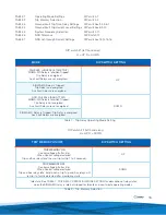
Page 17: ...is Idle Not Tripped Trip Relay is not energized Aux Fault Relays are not energized DOWN SIGMA MD Relay is Tripped Trip Relay is energized Aux Fault Relays are energized MODE DIP SWITCH SETTING Table 1...

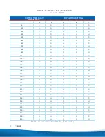
Page 18: ...U U D 1550 D U U U U 1650 U D D D D 1750 U D D D U 1850 U D D U D 1950 U D D U U 2050 U D U D D 2150 U D U D U 2250 U D U U D 2350 U D U U U 2450 U U D D D 2550 U U D D U 2650 U U D U D 2750 U U D U U...

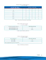
Page 19: ...y U UP D DOWN Table 4 Ground Fault Trip Current Level Settings SYSTEM FREQUENCY 60 50 Hz DIP SWITCH SETTING SYSTEM FREQUENCY 50 Hz UP SYSTEM FREQUENCY 60 Hz DOWN DIP switch 11 right hand array U UP D...

Page 20: ...CS 550 U D U D I GARD TxA Type ZSCS 600 U D U U I GARD TxA Type ZSCS 650 U U D D I GARD TxA Type ZSCS 700 U U D U I GARD TxA Type ZSCS 750 U U U D I GARD TxA Type ZSCS 800 U U U U I GARD TxA Type ZSCS...

Page 21: ...restored after a loss of control power the trip relay and auxiliary fault relays are returned to the state these relays had prior to the loss of control power The state of the trip relay and auxiliary...

Page 22: ...s open or presents some resistance Trip Time Less than 60 seconds per CAN CSA M421 00 Typically 3 5 seconds 0 100 msec Up to 10 seconds under certain conditions Accuracy NGR Trip Resistance limits in...

Page 23: ...the conductor on terminal G of the NGRS XX resistor sensor from ground and ensure the conductor is insulated 4 Disconnected the conductors between the X1 and X2 terminals of the TxA type ZSCS and the...

Page 24: ...in less than 1s if ground fault current exceeds 20 of the prospective ground fault current 3 6 2 Neutral Grounding Devices A neutral grounding device shall be a continuously rated except when ground f...

Page 25: ...24 Figure 2 Sigma MD Monitor Relay Detail A Typical NGRS Sensing Resistor Ngrs 6 Dual Voltage Model Shown Figure 3 Low Voltage NGRS Resistor Sensor...

Page 26: ...25 Figure 5 NGRS 50 Figure 4 NGRS 25...

Page 27: ...26 Figure 6 High Voltage NGRS Resistor Sensors...

Page 28: ...www i gard com Phone 905 673 1553 Toll Free 1 888 737 4787 Fax 905 673 8472 support i gard com...

Reviews: