7
4.1.3 Connections
Refer to Figure 2 for electrical connections to the SIGMA-MD monitor relay. Terminals on the relay will accept up to
#14 AWG wire. Connect control power to terminals L and N. An isolation transformer is recommended as the source
of supply to prevent excessive voltage being applied to the relay’s internal power supply.
Connect the G terminal on the SIGMA-MD monitor relay to a suitable grounding point. This grounding point should
be electrically common to the grounding point of the NGR.
The SIGMA-MD monitor relay must be grounded as described above. As the relay’s housing is non metallic,
no chassis bond is required. Connect the NGRS resistor sensor input terminal on the SIGMA-MD monitor relay
(terminal 45) to the R terminal of the NGRS-XX resistor sensor as shown in Figure 2. Connect the ZSCS input
terminals on the SIGMA-MD monitor relay to the X1 and X2 terminals on the TxA zero sequence current sensor as
shown in Figure 2.
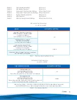
Refer to the description of the trip relay operating mode settings for an explanation of the shunt (non failsafe)
and undervoltage (failsafe) operating modes and the relay contact states for each of these operating modes. The
connection of field devices to the terminals of the SIGMA-MD monitor relay must be as specified in the installation
specifications. These include the trip relay terminals, the auxiliary fault relay terminals, the external reset, test and
the G/F meter terminals.
If door/panel mounted or remote test and/or reset controls are required, connect momentary single pole single
throw (SPST) normally open contact pushbuttons to the appropriate terminals on the SIGMA-MD monitor relay.
Refer to Figure 2.
If a panel/door mounted or remote ground fault meter is required, a meter conforming to specifications given in this
document can be connected to the appropriate terminals on the SIGMA-MD monitor relay. Refer to Figure 2. The
I-GARD GFU-AM1 percentage ammeter is designed for use in this application. If a meter other than the I-GARD
GFU-AM1 is used observe the polarity shown on the front panel and in Figure 2.
4.2 T
x
A TYPE ZERO SEQUENCE CURRENT SENSOR (ZSCS)
4.2.1 Location
The ZSCS should be mounted near the system transformer along with the NGRS-XX resistor sensor and NGR,
preferably on the low voltage (ground) end of the NGR. At higher voltages please refer to recommendations in the
ZSCS manual (C-700 EM).
4.2.2 Mounting
The overall dimensions of the Zero Sequence Current Sensor may be found in the C-700EM, T-sensor manual.
4.2.3 Connections
The neutral point of the system transformer is to be connected to the ungrounded end of the NGR such that this
conductor passes through the window of the Zero Sequence Current Sensor (ZSCZ).
The ZSCS secondary terminals, X1 and X2, must be connected to the appropriate terminals on the SIGMA-MD
monitor relay (47, 48) as shown in Figure 2.


