G8 CPCI Enclosure User’s Guide
ii
Table of Contents
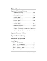
Appendix 1 Technical Reference
P1 Connector Pin Assignments . . . . . . . . . . . . . . . . . . . . . .A1-1
P1 Signal Descriptions . . . . . . . . . . . . . . . . . . . . . . . . . . . .A1-1
P2 Connector Pin Assignments . . . . . . . . . . . . . . . . . . . . . .A1-3
P2 Signal Descriptions . . . . . . . . . . . . . . . . . . . . . . . . . . . .A1-4
P3 Connector Pin Assignments . . . . . . . . . . . . . . . . . . . . . .A1-5
P3 Signal Descriptions . . . . . . . . . . . . . . . . . . . . . . . . . . . .A1-5
P4 Connector Pin Assignments . . . . . . . . . . . . . . . . . . . . . .A1-7
P4 Signal Descriptions . . . . . . . . . . . . . . . . . . . . . . . . . . . .A1-7
P5 Connector Pin Assignments . . . . . . . . . . . . . . . . . . . . . .A1-10
P5 Signal Descriptions . . . . . . . . . . . . . . . . . . . . . . . . . . . .A1-10
P4 Connector Pin Assignments (Computer Telephony Bus) .A1-13
P4 Signal Descriptions (Computer Telephony Bus) . . . . . . .A1-13
Appendix 2 Glossary of Terms
Appendix 3 Limited Warranty
Appendix 4 FCC Compliance
List of Figures
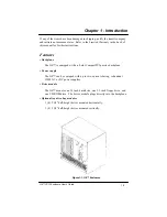
Figure 1-1
G8™ Enclosure . . . . . . . . . . . . . . . . . . . . . . .1-3
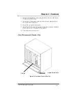
Figure 2-1
G8™ Enclosure (Rear) . . . . . . . . . . . . . . . . .2-3
Figure 2-2
Fan Access Door & Fan Tray . . . . . . . . . . . . .2-5
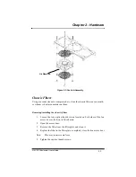
Figure 2-3
Fan Sub-Assembly . . . . . . . . . . . . . . . . . . . .2-7
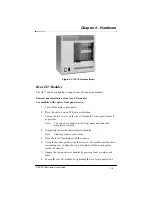
Figure 4-1
Drive Bay Module . . . . . . . . . . . . . . . . . . . . .4-1
Summary of Contents for G8
Page 1: ...G8 CPCI Enclosure User s Guide G8 8 Slot CompactPCI Enclosure User s Guide 095 30004 00 Rev A ...
Page 8: ...iv Table of Contents This page was intentionally left blank G8 CPCI Enclosure User s Guide ...
Page 20: ...2 8 G8 CPCI Enclosure User s Guide Chapter 2 Hardware This page was intentionally left blank ...


