


SECTION 2 FUNCTION
This multiple current LED driver has a wide range of loading capacity:
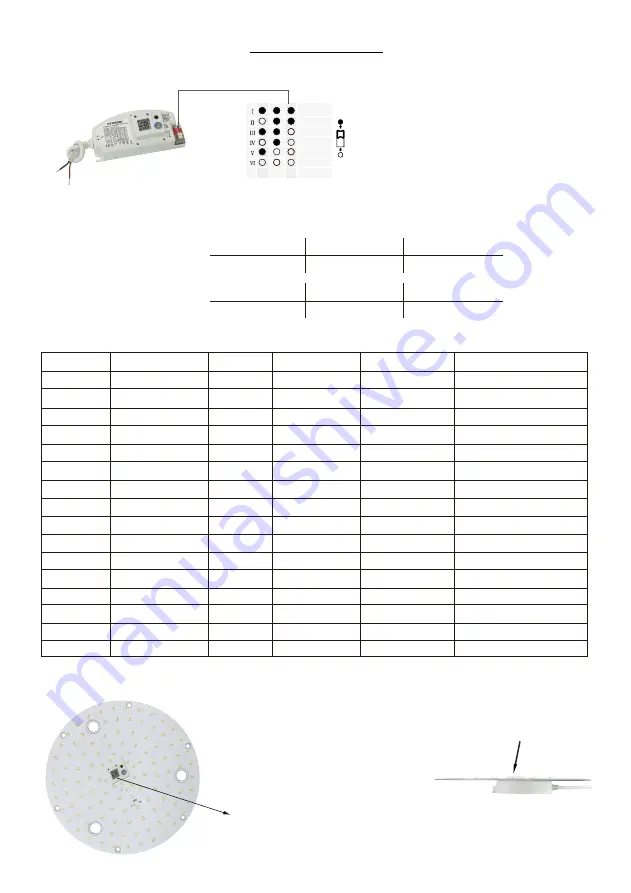
Maximum load @ different currents:
Maximum voltage @ different currents:
3.5~17W (350mA) 5~24W (500mA) 5.5~25W (550mA)
7~28W (700mA) 7~28W (750mA) 9~28W (900mA)
10~48V (350mA) 10~48V (500mA) 10~46V (550mA)
10~40V (700mA) 10~37V (750mA) 10~31V (900mA)
Current
350mA
500mA
550mA
700mA
750mA
900mA
1 2
3
The current can be easily configured by choosing
the correct combination of the DIP switches (see
table on the left).
2.1 LED Current Selections
2.2 LED Maximum Load and Voltage
2.3 Settings (Rotary Switch on Sensor Antenna)
Channel Detection range Hold-time Daylight sensor Stand-by period Stand-by dimming level
0
100%
5s
Disable
10s
10%
1
100%
30s
2Lux
1min
10%
2
100%
1min
2Lux
5min
10%
3
100%
1min
10Lux
10min
10%
4
100%
1min
Disable
+∞
10%
5
100%
5min
2Lux
10min
10%
6
100%
5min
10Lux
30min
10%
7
100%
5min
Disable
+∞
10%
8
100%
10min
2Lux
10min
10%
9
100%
10min
10Lux
30min
10%
A
100%
10min
Disable
+∞
10%
B
50%
10min
Disable
30min
10%
C
10%
10min
Disable
10min
10%
D
100%
30min
10Lux
30min
10%
E
100%
30min
Disable
+∞
10%
F
100%
5s
2Lux
10s
10%
2.4 Assembly
Note: end-user can also scan the QR
code on the housing for checking settings.
The sensor antenna features the rotary
switch and protrudes the LED panel.
This feature enables the end user to
access the sensor settings without
removing the gear tray / LED board.
Cut-out size: 36 x 29.5 (mm)
Sensor antenna


