background image

NOTE:  

Check your Parts Manual to make sure this

software applies to the Lift Truck you are servicing.

The  Truck  Configuration  screen  contains  several
drop-down  list  boxes  for  configuring  the  hydraulic
controller to the truck to which it is connected. See
Figure 7.

Users can select the desired unit of measure (impe-
rial  or  metric)  from  the  drop-down  list  box  on  the
right.

The  first  drop-down  list  box  on  the  left  lists  the
types of front-end valve. The carriage type and ac-
companying  valves  associated  with  the  truck  will
determine which choice to select. See Figure 8.

Figure 8. Front-End Valve Drop-Down List Box

The  next  drop-down  list  box  lists  the  possible  hy-
draulic input devices. See Figure 9.

Figure 9. Hydraulic Input Devices Drop-Down List

Box

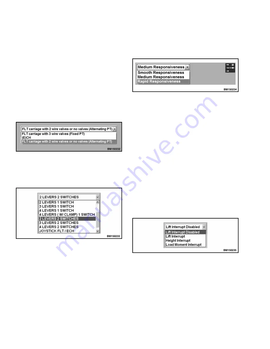
The next drop-down list box is for selecting the de-
gree  of  responsiveness  in  the  hydraulic  system.  In
addition,  a  hyper  link  displays  to  the  right  of  the

drop-down  list  box  representing  the  active  mode.
When clicked on, this link will take the user to the
appropriate  mode  definition  subscreen.  See  Fig-
ure 10.

Figure 10. Hydraulic Responsiveness Drop-Down

List Box

NOTE:   

The  Lift/Height  Interrupt  drop-down  list

box is an optional feature that can be enabled/disa-
bled  if  the  truck  has  the  necessary  hardware.  The
hardware may be obtained via SPED.

The Interrupt function limits the movement of the

mast  depending  on  the  appropriate  input.  For  the
lift  and  height  interrupt,  an  input  pin  on  the  con-
troller is defined and when this input is active the
movement  of  the  mast  is  interrupted.  See  Fig-
ure  11.  
For  Load  Moment  Interrupt,  the  pressure
signal  from  the  pressure  transducer  placed  in  the
lift section is used. This interrupt is active at a cer-
tain  pressure  signal  and  inactive  below  a  certain
pressure  signal.  Both  Lift/Height  Interrupt  and
Load  Moment  Interrupt  values  are  adjustable  at
the  service/technician  or  engineering  level  of  the
Hydraulic User Interface program.

Figure 11. Lift/Height Interrupt Drop-Down List

Box

General Functions of the Interface

2200 SRM 1481

16

Summary of Contents for H190HD2

Page 1: ...Hyster J007 H190HD2 H210HD2 H230HD2 H230HDS2 H250HD2 H280HD2 Forklift Service Repair Manual...

Page 2: ...XM 6 H300 330HD2 H019 H16 0XM 6 H360HD2 H019 H10 0 12 0XM 12EC H360HD2 EC H019 H13 16XM 6 H10 12XM 12EC H300 360HD2 H360HD2 EC J019 H8 12XM 6 H10XMS 6 H190 280HD2 H230HDS K007 H16XM 9 H18XM 7 5 H16XM...

Page 3: ...dic Maintenance section Keep the unit clean and the working area clean and orderly Use the correct tools for the job Keep the tools clean and in good condition Always use HYSTER APPROVED parts when ma...

Page 4: ...ult Flow Settings Screen 7 Features Screen 7 Loaded Speed Reduction Screen 7 Flow Settings Screen 7 General Functions of the Interface 8 Main Functional Requirements 8 What is Needed for the Hydraulic...

Page 5: ...the Hydraulic User Interface Program 36 Calibrating the Lever Without the Hydraulic User Interface Program 36 Calibrating the Joystick Without the Hydraulic User Interface Program 36 Fault Codes 37 C...

Page 6: ...ore information Please click here Then get the complete manual NOTE If there is no response to click on the link above please download the PDF document first and then click on it Have any questions pl...

Page 7: ...agrams 8000SRM1500 Electrical System 2200SRM1499 Description The hydraulic system is operated through an elec trically operated control valve that receives its sig nals from the hydraulic controller S...

Page 8: ...l signals for ON OFF functions or CAN bus messages for other linked controllers The controller continually monitors the system for fault conditions displays the appropriate fault co des and takes acti...

Page 9: ...of the con trol valve section Red indicates a sticking spool or an internal error in the actuation module Flashing Red indicates an input signal fault Cycling the ignition key resets the LED to Green...

Page 10: ...e of the following interrupt functions can be configured in the Hydraulic User Interface program from the Truck Configuration Screen Operator Presence System OPS The OPS has an electrical switch in th...

Page 11: ...s which determines the valve flow in one direc tion only The direction of the hydraulic function is determined by a separate valve that receives a sep arate digital signal Analog outputs are used for...

Page 12: ...Maximum Engine Speed Temperature Maximum Rpm 5 C 23 F Unrestricted 10 C 14 F 1600 13 C 9 F 1200 20 C 4 F 1000 High Temperature Protection Optional The High Temperature Protection feature limits ve hi...

Page 13: ...ry 3 decrease ramp time Twist Lock pressure increase ramp time Twist Lock pressure decrease ramp time Set Default Flow Settings Screen This screen consists of three parameters pumps mast and carriage...

Page 14: ...the program double click the in stallation icon The program automatically installs the Hydraulic User Interface Program and all re quired drivers for the IFAK interface cable After installation is com...

Page 15: ...Mode Screen Smooth Medium Rapid Limited Auxiliary2 increase time Auxiliary2 decrease time Auxiliary3 increase time Auxiliary3 decrease time Twist Lock increase time Twist Lock decrease time Default F...

Page 16: ...owering Limit Max Tilt Forward Limit Max Tilt Backward Limit Max Aux0 Limit Max A Aux0 Limit Max B Aux1 Limit Max A Aux1 Limit Max B Aux2 Limit Max A Aux2 Limit Max B Aux3 Limit Max A Aux3 Limit Max B...

Page 17: ...Ver number of the in terface program and the corresponding part num ber PN See Figure 4 The truck s serial number is programmed into the hydraulic controller with the ROP Read Only Pa rameter File The...

Page 18: ...reen click on the Upload Parameters button or press the F2 key Clicking on the Click here to Continue button advances the program to the Truck Configuration screen Basic Screen Layout of the Hydraulic...

Page 19: ...CREEN ICON 3 CALIBRATION SCREEN ICON 4 FLOW SETTINGS SCREEN ICON 5 VALVE SETTINGS SCREEN ICON 6 DIAGNOSTIC SCREEN ICON 7 ACTIVE ERROR SCREEN ICON 8 ACTIVE ERROR INDICATOR Figure 6 Screen Layout 2200 S...

Page 20: ...ntroller See also Calibration 4 Flow Settings Screen Adjusts flow demands of lift tilt and all auxiliary functions 5 Valve Settings Screen Displays the settings for the electric hydraulic valves Servi...

Page 21: ...Truck Configuration Screen Figure 7 Truck Configuration Screen 2200 SRM 1481 General Functions of the Interface 15...

Page 22: ...list box representing the active mode When clicked on this link will take the user to the appropriate mode definition subscreen See Fig ure 10 Figure 10 Hydraulic Responsiveness Drop Down List Box NO...

Page 23: ...deceleration ramp times can be defined for each function within reasonable limits for each analog function See Table 3 Figure 12 il lustrates the different ramping time behavior for jumping input Up...

Page 24: ...Figure 7 Using the serial number of the truck the hydraulic controller automatically selects the pump settings Check this selection against actual installed parts and press the F4 key to save the pum...

Page 25: ...e via the Truck Con figuration screen by clicking on the Truck Configu ration icon Settings for Cut In Pressure and Cut Out Pressure are adjustable The Cut In Pressure value is set from where the Load...

Reviews: