FLYBACK DIODES
Some components induce current surges when they
are switched off. These surges can cause sparking
of mechanical contacts in switches and relays,
which results in premature erosion of these con-
tacts. Flyback diodes prevent these symptoms by
connecting the induced current surge to ground.
Always check functionality of a flyback diode when
a switch or relay has failed. In most cases a failed
diode will not conduct at all. Sometimes a failed di-
ode causes a short circuit.
Replacement diodes are integrated in connectors
that attach the correct diode polarity to the wire
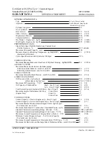
harnesses. Table 8 provides a complete listing of all
flyback diodes fitted.
Table 8. Flyback Diodes
Connector
Diode Description
Location
Harness Name
Figure Number
CPS17
Diode_Main_Power
[24,A], [27,C]
Sideconsole
17
CPS172
Diode_Neutral_Signal
[27,C], [29,D]
Sideconsole
17
CPS18
Diode_Hydraulic_contr
oller
[138,D]
Sideconsole
17
CPS236
Diode_Cab_Tilt_Pump
[108,F]
Powered Cab Tilt
N/A
CPS34
Diode_Calibration
[62,C]
Sideconsole
17
CPS39
Lights_Diode
[122,C], [75,I]
Sideconsole
17
CPS54
Backup_Diode
[87,F]
Rear
N/A
CPS82
Diode_Horn
[162,D]
Cab Underfloor
18
CAN (CONTROLLER AREA NETWORK)
CANbus is a standard for an electronic system that
allows communication between different controllers
without the need for a host computer.
The different controllers have their own controlled
network of sensors, actuators and control devices.
Functioning of these components cannot be influ-
enced by other controllers unless the programming
of a network controller specifically allows.
Each controller requires its own voltage supply to
feed the controller and to provide signals to the
components that belong to the controller network.
Without voltage supply a controller does not func-
tion.
Communication occurs through sending and receiv-
ing signals. Each signal contains amongst others a
code for the type of message (e.g. coolant tempera-
ture), the message itself (83°) and the ID of the con-
troller (ECM) that has sent the signal. Each con-
troller has been programmed to react only to cer-
tain messages from certain controllers. All other
messages are ignored.
Only two wires (wire 900 and 901) are required for
communication: The data wire and the data inverse
wire. Integrity of signal transfer is verified by com-
paring the return signal of the data inverse wire
with the original signal of the data wire.
The CANbus system includes the following control-
lers:
• Engine Control Module
• Transmission controller
• Hydraulic controller
• Instrument cluster
• Diagnostic connector*
(*) The diagnostic connector itself is not a control-
ler. Instead, the IFAK cable that leads to the laptop
computer contains the controller that will make
contact with the CANbus system when plugged into
the diagnostic connector.
All sensors that belong to one system controller are
shown on one sheet of the electrical diagram.
2200 SRM 1944
Electrical Schematic and System Description
17