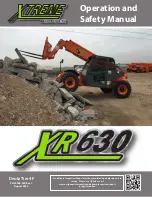
background image

LIFTING

The lift cylinders are supported at the base of the
outer mast. When the cylinders extend, they push
the inner mast upwards. The chains are attached to
the outer mast and the carriage, and they run over
the chain sheaves at the top of the inner mast.
When the inner mast moves upwards, the chains
pull the carriage upwards to twice the distance that
the lift cylinders have extended. See Figure 4.

Operation

The lift cylinders extend when the hydraulic
pressure applied is sufficient to lift the combined
weight of the load, forks, carriage and inner mast.
The raised position of the mast is maintained by
hydraulically closing off the piston side of the lift
cylinders. Lowering is achieved by releasing
hydraulic pressure, which is induced by the weight
resting on the rod of the lift cylinders.

1. LIFT CYLINDERS

2. OUTER MAST

3. INNER MAST

4. CHAIN SHEAVE

5. LIFT CHAIN

6. CARRIAGE

Figure 4. Operation of a Two-Stage Mast

Lifting speed and lowering speed are controlled by
the moved position of the lift spool in the main
control valve. Maximum lifting speed is determined

by maximum pump supply. Maximum lowering
speed is determined by the lowering control valve at
the bottom of each lift cylinder.
The lowering control valve is a pressure
compensated valve. It allows an increasing flow
with increasing pressure until a preset maximum
flow is reached. The result is that similar lowering
speeds are obtained for loaded and unloaded
conditions. The primary function of the lowering
control valve is to limit the lowering speed in case of
a malfunction of the supply/return connection.
The different lift height capacities are determined
by the dimensions of the various mast assemblies.
The lowest position of the forks is determined by the
adjustment of the chain anchors.

Pilot Operated Check Valves

The lift spool in the main control valve does not seal
completely in the neutral position. To obtain zero
leakage, a pilot operated check valve is mounted in
the main control valve between lift spool and lift
cylinder. See Figure 5.
When raising the mast, oil supply will pass through
a check valve in the pilot operated check valve. To
lower the mast, the pilot operated check valve must
be moved into the open position.
The position of the pilot operated check valve, is
determined by oil pressure at the cylinder side of
the check valve, and by the combined force of a
spring and the oil pressure at the pilot side of the
check valve. Spring force will keep the check valve
closed when equal pressures exist at the pilot side
and cylinder side of the check valve.
The pilot operated check valve opens when pressure
is removed from the pilot side of the check valve,
which connects with the selector valve. The selector
valve opens when the lift spool has moved into the
lowering position, which allows pilot pressure from
the spool to reach the selector valve. After the
selector valve has opened and drained pilot pressure
from the pilot operated check valve, the oil from the
lift cylinders will drain through the check valve and
lift spool to the tank.

4000 SRM 1664

Description And Operation

3

Summary of Contents for A238

Page 1: ...MAST H16XM9 12 H18XM 7 5 9 H360 36HD H360 48HD A238 B238 PART NO 4097319 4000 SRM 1664...

Page 2: ...dic Maintenance section Keep the unit clean and the working area clean and orderly Use the correct tools for the job Keep the tools clean and in good condition Always use HYSTER APPROVED parts when ma...

Page 3: ...rd Carriage with Manual Fork Positioning 10 Standard Carriage with Hydraulic Fork Positioning 10 Integral Side Shift ISS Carriage with Pin Type Forks 11 Dual Function Side Shift and Fork Positioning C...

Page 4: ...Positioner Cylinder for DFSSFP Carriage 32 Clean and Inspect 32 Assemble Fork Positioner Cylinder for DFSSFP Carriage 33 Install 34 Side Shift Cylinder 34 Remove 34 Disassemble 34 Clean and Inspect 35...

Page 5: ...ion Check 59 Mast Operation Check 60 Fork Inspection 60 Lift Chains 61 Lift Chains Cleaning 61 Lift Chain Inspection 61 Lift Chain Lubricant Requirements 62 Lift Chain Lubrication Procedure 62 Leak Ch...

Page 6: ...ar shaking Movement or Slight Carriage Movement When Starting Engine 73 Unequal Movement of Left And Right Tilt Cylinder 73 Insufficient Lifting Speed 73 Insufficient Lifting Capacity 73 Incorrect Low...

Page 7: ...ast are provided by the tilt cylinders Different carriage options exist for side shifting fork positioning or for attachments The masts for H16XM 9 H18XM 7 5 H360 36HD and H16XM 12 H18XM 9 H360 48HD t...

Page 8: ...ston side is limited by the 19 MPa 2756 psi relief valve at port A Extruded oil from the rod side has to pass the pilot operated check valve that opens if oil pressure at the piston side is at least 2...

Page 9: ...e primary function of the lowering control valve is to limit the lowering speed in case of a malfunction of the supply return connection The different lift height capacities are determined by the dime...

Page 10: ...The area between shell and rod is closed off by a 1 MPa 145 psi check valve which is located at the lower cross member of the outer mast The function of the 1 MPa 145 psi check valve is to retain air...

Page 11: ...ce Operation The emergency lowering valve is located at the left hand side of the main control valve and can be accessed after removal of the cover above it See Figure 6 Initial turning of the hand wh...

Page 12: ...damaged The link pins are riveted into the outer plates The press fit of the link pins in the outer plates is essential for the integrity of the chain The inner plates have a tight sliding fit for an...

Page 13: ...and plates is pushed away under load conditions and must be allowed to restore daily by removing the load and allowing oil to penetrate again Restoring the oil film is effected by the capillary action...

Page 14: ...ents for Chain Lubricant The chain lubricant must be a mineral or synthetic engine oil Oil viscosity must match the ambient temperature so that the oil remains viscous and can penetrate to the contact...

Page 15: ...handling On the carriage the bearing blocks are located just above the load rollers On the mast the lower bearing blocks are above the lower rollers on the inner mast The upper bearing blocks are at t...

Page 16: ...k Positioning The pin type forks are positioned by fork guides that are attached to the fork positioning cylinders By activating the directional control valve the cylinders move the guides and forks i...

Page 17: ...he cab the forks can be side shifted positioned individually or positioned simultaneously The forks are either quick disconnect hook type forks or they have a design which integrates the function of t...

Page 18: ...rol valve port T Aux Alternating Pressure and Tank P T Alternating P T is applied when a limited number of functions allow the control valve on the truck to determine the direction of the oil flow Exa...

Page 19: ...f the directional control valve Harness connectors for unused functions are folded back and taped in An additional splitter harness is installed for DFSSFP carriages with simultaneous fork positioning...

Page 20: ...E HOUSING 2 INLET MODULE 3 RELIEF VALVE 4 PILOT PRESSURE SUPPLY VALVE 5 SOLENOID 6 CYLINDER Figure 17 Directional Control Valve Schematic SS Carriage with FP shown Description And Operation 4000 SRM 1...

Page 21: ......

Reviews: