background image

2

EDGE Pro and MicroEDGE Pro CNCs

 Field Service Bulletin 808280

Repositioning SERCOS II and SERCOS III boards in the EDGE Pro CNC

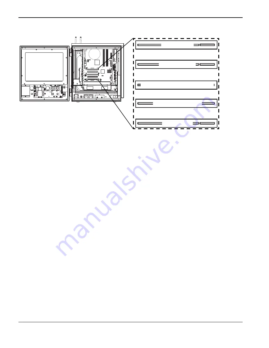
Location of boards in EDGE Pro PCI slots

As you follow this procedure, set aside all screws and other hardware for reuse.

To open the CNC enclosure: 

1.

To open the front panel, use a 5/16-inch wrench to remove the three screws at the top of the panel and the three 
screws at the bottom of the panel.

2.

To open the side, use a 5/16-inch wrench to


remove the two screws at the top of the panel and the two screws at the 

bottom of the panel.

To remove the SERCOS II or SERCOS III master board:

1.

Remove the RX and TX cables from the outside edge of the board.

2.

Use a #1 Phillips screwdriver to remove the screw in the mounting frame.

3.

Pull the board from PCI slot 3 on the motherboard.

To reposition the utility and serial isolation board: 

1.

 Remove the serial cables from the left side of the board:

a.

Use a #1 Phillips screwdriver to remove the screws from either side of the serial cable connectors.

b.

Remove the grey and multicolored ribbon cable connectors from the serial connectors on the left side of the 
board.

c.

Remove the screw that holds the silver board bracket to the side of the subchassis.

You do not need to remove any other cables from the connectors on the board.

2.

Use a #1 Phillips screwdriver to remove the screw from the standoff at the right front of the board.

Slot 1

Slot 2

Slot 3

Slot 4

Slot 5

SERCOS II or SERCOS III master board

Wireless board

Not used

Utility/serial isolation board

Not used

Summary of Contents for SERCOS II

Page 1: ...Field Service Bulletin 808280 Revision 0 December 2013 Repositioning SERCOS II and SERCOS III Boards in EDGE Pro and MicroEDGE Pro CNCs ...

Page 2: ...lding 495 ShangZhong Road Shanghai 200231 PR China 86 21 60740003 Tel 86 21 60740393 Fax Hypertherm Europe B V Vaartveld 9 4704 SE Roosendaal Nederland 31 165 596907 Tel 31 165 596901 Fax 31 165 596908 Tel Marketing 31 165 596900 Tel Technical Service 00 800 4973 7843 Tel Technical Service Hypertherm Japan Ltd Level 9 Edobori Center Building 2 1 1 Edobori Nishi ku Osaka 550 0002 Japan 81 6 6225 11...

Page 3: ...oEDGE Pro CNCs as a first step in addressing these performance issues Tools and materials needed 1 Phillips screwdriver 5 16 inch wrench or socket 1 4 inch wrench Contents of kit 428305 WARNING ELECTRIC SHOCK CAN KILL Disconnect electrical power before performing any maintenance Only qualified personnel can work inside the CNC cabinet with AC power connected See the Safety section of the system s ...

Page 4: ... of the board 2 Use a 1 Phillips screwdriver to remove the screw in the mounting frame 3 Pull the board from PCI slot 3 on the motherboard To reposition the utility and serial isolation board 1 Remove the serial cables from the left side of the board a Use a 1 Phillips screwdriver to remove the screws from either side of the serial cable connectors b Remove the grey and multicolored ribbon cable c...

Page 5: ... 10 lb in 9 Plug the serial cables into the left side of the board a Plug the grey ribbon cable into the Serial 2 connector b Plug the multicolored ribbon cable into the Serial 1 connector 10 Fasten the screws on either side of both serial cable connectors and tighten them to 0 67 N m 6 lb in To replace the SERCOS II or SERCOS III board 1 Insert the SERCOS II or SERCOS III board into PCI slot 4 on...

Page 6: ...hem to 3 39 N m 30 lb in After you reposition the boards After a SERCOS II update if you cannot establish the ring verify that the RX and TX fiber optic cables are securely plugged into the correct connector LED 1 for the RX port should be illuminated in green For more details see the EDGE Pro SERCOS II Instruction Manual 807640 After a SERCOS III update if you cannot establish the ring verify tha...

Page 7: ...r to remove the screw that connects the PCI bracket at the side of the board to the enclosure 3 Pull the board from PCI slot 3 on the motherboard To reposition the wireless board 1 Disconnect the antennas or antenna cables from the connectors on the back of the CNC 2 Use a 1 Phillips screwdriver to remove the screw that connects the PCI bracket to the enclosure 3 Pull the wireless board from PCI s...

Page 8: ...n MicroEDGE Pro PCI slots After you reposition the boards Moving the wireless card may reset network passwords and IDs If the controller does not connect to the network refer to the MicroEDGE Pro Instruction Manual for wireless setup information After a SERCOS II update if you cannot establish the ring verify that the RX and TX fiber optic cables are securely plugged into the correct connector LED...

Reviews: