PORT PROCESSORS/MODULES
940043-002
INTEGRATED ENTERPRISE NETWORK
3-21
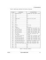
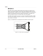
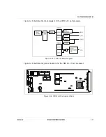
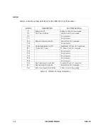
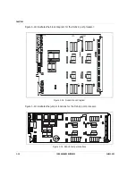
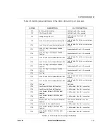
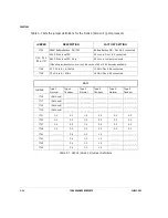
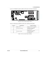
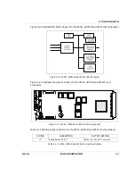
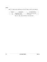
Table 3-5 lists the jumper definitions for the DLA14 (Version D) port processor.
Table 3-5 DLA14 (Version D) Jumper Definitions
JUMPER
DESCRIPTION
FACTORY SETTING
JT1
SCC Clock 8/16/19MHz
19MHz: Pins 5 & 6 connected.
JT2
CPU Clock 8/16MHz
16MHz: Pins 2 & 3 connected.
JT3
Battery Backup On/Off
Battery Backup On: Pins 2 & 3
connected.
JT9
Line 4 M Lead Control System Battery/-48V
Refer to Table 3-6 for the correct jumper
settings.
JT10
Line 3 M Lead Control System Battery/-48V
Refer to Table 3-6 for the correct jumper
settings.
JT11
Line 4 DC Ring Detect Bypass Enabled/
Disabled
Bypass Enabled: Pins 1 & 2 connected.
JT12
Line 3 DC Ring Detect Bypass Enabled/
Disabled
Bypass Enabled: Pins 1 & 2 connected.
JT13
Line 4 E Lead Control System Battery/-48V
Refer to Table 3-6 for the correct jumper
settings.
JT16
Line 3 E Lead Control System Battery/-48V
Refer to Table 3-6 for the correct jumper
settings.
JT17
Line 2 DC Ring Detect Bypass Enabled/
Disabled
Bypass Enabled: Pins 1 & 2 connected.
JT18
Line 1 DC Ring Detect Bypass Enabled/
Disabled
Bypass Enabled: Pins 1 & 2 connected.
JT19
Not Used
Not Used
JT20
Line 2 E Lead Control System Battery/-48V
Refer to Table 3-6 for the correct jumper
settings.
JT21
Line 1 E Lead Control System Battery/-48V
Refer to Table 3-6 for the correct jumper
settings.
JT22
Not Used
Not Used
JT23
Back Plane -48V Enabled/Disabled
-48V Enabled: Pins 1 & 2 connected.
JT24
Back Plane -48V Enabled/Disabled
-48V Enabled: Pins 1 & 2 connected.
JT25
Line 1 System Battery to -48V Enabled/
Disabled
-48V Enabled: Pins 1 & 2 connected.
JT26
Line 2 System Battery to -48V Enabled/
Disabled
-48V Enabled: Pins 1 & 2 connected.
JT27
System Ground to Telco Ground Enabled/
Disabled
Telco Ground Enabled: Pins 1 & 2
connected.
JT28
On Board -48V Enabled/Disabled
-48V Enabled: Pins 1 & 2 connected.
JT29
Line 3 System Battery to -48V Enabled/
Disabled
-48V Enabled: Pins 1 & 2 connected.
JT30
Line 4 System Battery to -48V Enabled/
Disabled
-48V Enabled: Pins 1 & 2 connected.
Summary of Contents for IEN 1000
Page 4: ......
Page 10: ...TABLE OF CONTENTS VI IEN HARDWARE REFERENCE 940043 002 ...
Page 11: ...C H A P T E R 1 Introduction In This Chapter IEN Hardware Reference 1 3 ...
Page 12: ......
Page 14: ...CHAPTER 1 1 4 IEN HARDWARE REFERENCE 940043 002 ...
Page 16: ......
Page 48: ......
Page 108: ...CHAPTER 3 3 62 IEN HARDWARE REFERENCE 940043 002 ...
Page 110: ......
Page 164: ...CHAPTER 4 4 56 IEN HARDWARE REFERENCE 940043 002 ...
Page 166: ......
Page 180: ...CHAPTER 5 5 16 IEN HARDWARE REFERENCE 940043 002 ...
Page 181: ...C H A P T E R 6 System Configuration In This Chapter IEN 1000 Configuration 6 3 ...
Page 182: ......
Page 190: ...CHAPTER 6 6 10 IEN HARDWARE REFERENCE 940043 002 ...
Page 196: ......
Page 197: ......
Page 198: ...Printed in the United States P N 940043 002 Network Systems ...

