2-24
IEN HARDWARE REFERENCE
940043-002
C
HASSIS
P
ORT
P
INOUTS
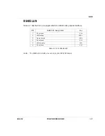
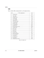
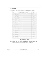
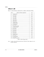
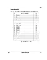
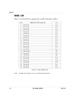
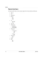
This section describes the pin assignments associated with each of the chassis. The pin
assignments are divided up by connector type, RJ11 and DB25, and interface.
Note:
The signal assignments for the IEN chassis port interface connectors are determined by the
port interface card located in the associated card slot.
n
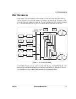
Refer to Chapter 3, Port Processors/Modules for more information about a specific port
processor.
n
Refer to page 2-5, IEN 1000 for more information about the IEN 1000 chassis
specifications.
n
Refer to page 2-8, IEN 2000 for more information about the IEN 2000 chassis
specifications.
n
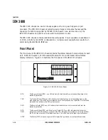
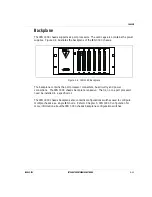
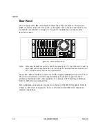
Refer to page 2-10, IEN 3000 for more information about the IEN 3000 chassis
specifications.
n
Refer to page 2-13, IEN 4000 for more information about the IEN 4000 chassis
specifications.
n
Refer to page 2-17, IEN 5000 for more information about the IEN 5000 chassis
specifications.
T1
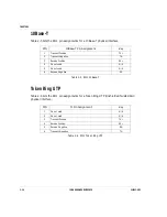
Table 2-2 lists the RJ11 pin assignments for a T1 physical interface.
Table 2-2 RJ11 T1
PIN
T1 Pin Assignment
Key
1
Receive Ring
RR
2
Receive TIP
RT
3
Transmit Ring
TR
4
Transmit TIP
TT
5
Ground
T
6
RC
T1
Summary of Contents for IEN 1000
Page 4: ......
Page 10: ...TABLE OF CONTENTS VI IEN HARDWARE REFERENCE 940043 002 ...
Page 11: ...C H A P T E R 1 Introduction In This Chapter IEN Hardware Reference 1 3 ...
Page 12: ......
Page 14: ...CHAPTER 1 1 4 IEN HARDWARE REFERENCE 940043 002 ...
Page 16: ......
Page 48: ......
Page 108: ...CHAPTER 3 3 62 IEN HARDWARE REFERENCE 940043 002 ...
Page 110: ......
Page 164: ...CHAPTER 4 4 56 IEN HARDWARE REFERENCE 940043 002 ...
Page 166: ......
Page 180: ...CHAPTER 5 5 16 IEN HARDWARE REFERENCE 940043 002 ...
Page 181: ...C H A P T E R 6 System Configuration In This Chapter IEN 1000 Configuration 6 3 ...
Page 182: ......
Page 190: ...CHAPTER 6 6 10 IEN HARDWARE REFERENCE 940043 002 ...
Page 196: ......
Page 197: ......
Page 198: ...Printed in the United States P N 940043 002 Network Systems ...

