●
If the clearance is out of specification, first remove the
cam chain tensioner, camshaft housing, camshaft.
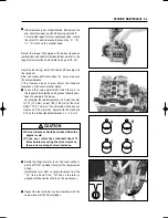
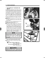
To install the tappet shim at original position, record
the shim NO. and clearance to present by
“
A
”
,
“
B
”
,
“
C
”
,
“
D
”
mark on the cylinder head.
Select the tappet that agree with tappet clearance
(vertical line) and shim NO.(horizontal line) as refer to the
tappet shim selection chart. (Refer to page 8-29
∙
30)
Adjust valve timing, install the camshaft housing and
the tensioner.
After the crankshaft rotate about 10 times, measure
the valve clearance.
If the clearance be not agree, adjust the standard
clearance as the same manner above.
●
In case that valve adjustment which there is no
the tappet shim selection chart, please follow instruc-
tions of example in the below.
For example, the intake clearance is 0.4 and the shim
is 170 (1.70 mm), select 195 (1.95 mm) of the shim
which 170 (1.70 mm) of the shim add up the excess
clearance 0.25 mm when adjust with the standard
0.15 as the intake standard clearance 0.1
�
0.2 mm.
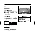
B
D
A
C
CAUTION
�
Valve clearance should be checked when the
engine is cold.
�
If you
don
’
t
rotate the crankshaft about 10
times before measuring the valve clearance,
there is no meaning of valve clearance.
●
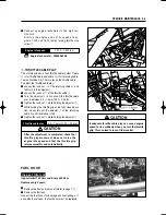
Rotate the magneto rotor to set the rear cylinder
’
s
piston at TDC(Top Dead Center) of the compression
stroke.
(Rotate the rotor 285
�
counter-clockwise from the
“
|
F
”
line, and until the
“
|
R
”
line on the rotor is
aligned with the center of hole on the crankcase.)
●
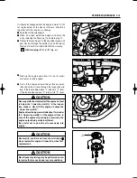
Inspect the rear cylinder
’
s valve clearance with the
same manner of the front cylinder.
PERIODIC MAINTENANCE 2-4
Summary of Contents for GT 650
Page 5: ...NOTE Difference between photographs and actual motorcycles depends on the markets ...
Page 13: ...1 7 GENERAL INFORMATION EXTERIOR ILLUSTRATION ...
Page 102: ...CARBURETOR 4 3 FUEL SYSTEM ...
Page 138: ...LAMP HEADLAMP TURN SIGNAL LAMP TAIL BRAKE LAMP ELECTRICAL SYSTEM 6 16 ...
Page 158: ...7 15 CHASSIS FRONT FORK ...

