background image


                                                                                                                                                Page 18

5. Installation

5.1 Basic prequisites for operating the Water-

Line softener device

The following requirements must be met for operating the Water-
Line softener device:

Electrical connection requires on-site fusing and must not 
be interrupted at any time (connection to branch circuit not 
permissable)

Minimum flow pressure must be 2.5 bar

Maximum flow pressure must not exceed 7.0 bar. Opti-
mum is 4.0 bar

Temperatur in operating room must be between 5 °C and 
40 °C

R.h. in operating room must not exceed 60 percent

The drain provided by customer must be a free outlet 
according to EN DIN 1717 

The operating room must be sufficiently ventilated, must 
allow for the floor loading introduced by the  WaterLine 
softener device and feature a floor gully. 

5.2 Selecting the correct installation location of

the Waterline softener device within the
house installation scenario

If  no mounting block is used, the house installation tubing 
must be cut at a suitable spot (downstream of the pressure 
reducer, if applicable) and the Waterline softener device 
must be inserted


For insertion of a mounting block approx. 300 mm of free 
tubing is required

Should a water filter not be installed yet, another 300 to 
400 mm of free tubing for installation of a filter must be 
considered

Water filter

Pressure

reducer

Consumer

soft water

By-pass

Flush tap
(optional)

Mounting block

Sampling tap

 (optional)

Fine-dosing for
soft water blending

softener device

to

from

System separator

Principle connection of HygroMatik WaterLine softener devices by means of the 

optional mounting block

Raw water

Summary of Contents for WaterLine Double

Page 1: ...Softener devices WaterLine Single WaterLine Double WaterLine Double Plus ÁWLSDP ENUÈ WLSDP EN Operating manual ...

Page 2: ...rsonnel only All electrical installation and servicing of the electrical components of this unit to be performed by qualified electricians only Disconnect power supply before installa tion and servicing Copyright HygroMatik GmbH 04 05 2015 WL S D DP EN All rights reserved ...

Page 3: ... 5 Brine 17 5 Installation 18 5 1 Basic prequisites for operating the WaterLine softener device 18 5 2 Selecting the correct installation location of the Waterline softener device within the house installation scenario 18 5 3 Requirements on the installation site of the WaterLine softener device 19 5 4 Set up of the WaterLine pendulum devices WL D DP 19 5 5 Attaching the tubing for raw water and s...

Page 4: ... by the device operator 30 8 2 1 Daily check of proper device operation 30 8 2 2 Periodical inspection 32 8 2 3 Minor Maintenance 32 8 3 Full maintenance 34 8 4 Troubleshooting 34 9 Removal from service storage and recommissioning 35 9 1 Removal from service 35 9 2 Storage 35 9 3 Recommissioning 35 10 Optional chlorine cell 36 10 1 Functional description and design 36 10 2 Mounting the device 36 1...

Page 5: ...s ment for the production of soft water It may only be used according to its intended use Caution Proper use includes fulfilment of the assembly disas sembly reassembly start up operating and maintenance condi tions specified by us as well as disposal measures Only appointed qualified staff may work on or with the system Persons transporting or working on or with the system must have read and unde...

Page 6: ...443 1 implemented in front of the water intake is obligatory Without such a filter the ion exchanger resin might silt up within short periods of time Also the control valve might get damaged by dirt ingress 1 2 Typographic markings lists with items beginning with bullets general lists lists with items beginning with arrows work or operating steps which should or must be carried out in the speci fi...

Page 7: ...d of in accordance with statutory requirements Please note precedes explanations for or cross references to other places in the text Also information is marked in this way that requires particular observance General safety instructions for working on the HY EKB20 softener device Caution Prior to working on the softener device water supply must be cut Caution The device may be under pressure Prior ...

Page 8: ...n the device On functional failures switch off the device immediately and secure against switching on again Clear any faults on the spot After repair work operational safety must be assured by expert staff Only use orignal spare parts All other national regulations beyond the a m coverage apply without restriction for operating the device Use by persons not entitled This device is not intended for...

Page 9: ... never to touch electrical components with wet hands Switch off the system immediately if faults in the electrical energy supply occur Only use original fuses with the specified amperage Inspect the system s electrical equipment at regular intervals Promptly eliminate deficiencies such as loose connections or melted cables After carrying out the corresponding electrical assembly or maintenance wor...

Page 10: ...hich notification of the transport company must occur for the purposes of identifying the damage are as follows Periods are subject to change without notice 3 4 Scope of delivery The following items are included in the delivery Softener device in case od a device featuring two pres sure tanks the second tank is separately packaged Operating manual s Accessories ordered 3 5 Packaging and return con...

Page 11: ...c condi tions Otherwise the softener may be prone to microbial con tamination if no water flow exists due to longer periods of non usage e g during holiday periods Pre setting for forced regen eration is 3 days This setting may be changed by the operator Since the WaterLine WL S softener device features only one pressure tank the device is not available for soft water produc tion during regenerati...

Page 12: ...enerations waste water connection Soft water connection Brine tank Brine tube Raw water connection Resin filling Riser pipe Overflow Floor drain Riser pipe w ball valve Pressure tank Inserted Riser pipe Top nozzle Bottom nozzle Inserted floor screen only when resin capacity is 100 m3 x dH or higher floor screen Brine filling Waste water hose Principle design of WaterLine softener device WL D DP Br...

Page 13: ...lay for time of the day presen tation as well as the preset and programmable parameters of the ion changer process Operating and programming is accom plished by use of the 5 keys designated SET CLOCK NEXT REGEN as well as Δ und up down arrows for increasing decreasing settings Control valve for WL D DP connections Brine tube connection Waste water Connection head for 2nd pressure tank Soft water R...

Page 14: ...ener device The control valve guides raw water into the pressure tank filled with exchanger resin Raw water flows top down through the resin while the resin absorbes magnesium and cal cium ions exchanging them with sodium ions By this mecha nism softened water is generated The product water enters the rise pipe in the pressure tank through the bottom nozzle and is subsequently propagated to the co...

Page 15: ...oncentration for the regeneration process The diluted brine is fed through the resin top down Now ion exchange takes place in the inverted direction as compared to softening setting free and draining calcium and magnesium ions bonded by the resin Following brining slow wash is carried out in the follow ing way When no more brine is sucked by the injector only raw water flows through the resin bed ...

Page 16: ...e betwwen1 30 mins und 4 30 mins depending on device capacity Brining is described in more detail in the following chapter Model Resin volume l Amount of salt kg Full brining Partial brining WL S 20 5 1 1 0 8 WL S 40 10 2 2 1 6 WL S 60 15 3 3 2 4 WL S 80 20 4 4 3 2 WL D 20 5 1 1 0 8 WL D 40 10 2 2 1 6 WL D 60 15 3 3 2 4 WL D 80 20 4 4 3 2 WL D 100 25 5 5 4 WL D 160 40 8 8 6 4 WL D 200 50 11 8 WL D...

Page 17: ...sumed during regenera tion full or partial brining is refered to For a residual hardness of soft water below 0 1 dH only full brining is adequate Full brin ing requires the use of 220g of salt per liter of resin Please note When working with zero hardness water zinc coated pipes must not be used Only pipes made from plastic or stainless steel are adequate In case of a lower requirement concerning ...

Page 18: ...roduced by the WaterLine softener device and feature a floor gully 5 2 Selecting the correct installation location of the Waterline softener device within the house installation scenario If no mounting block is used the house installation tubing must be cut at a suitable spot downstream of the pressure reducer if applicable and the Waterline softener device must be inserted For insertion of a moun...

Page 19: ... transportation safety reasons the second pressure tank is separatly packed Before operating the system the tubing between the corresponding connections on the control valve on top of the one pressure tank and the connecting head on the other pressure tank must be put in place The connecting tube coupling nuts must only be secured hand tight 5 5 Attaching the tubing for raw water and soft water 5 ...

Page 20: ...lastic or stainles steel Zinc plated pipes are not suitable for use with zero hardness water 5 5 2 Connecting the control valve to the house water installation Use adequate hoses incl flat gaskets to connect water inlet and water outlet of the control valve to the house water installation Make sure to pay attention to the flow direction arrows on the control valve indicating water inlet and water ...

Page 21: ... the softener system in order not to allow any water from the softener to enter the house installation before clean soft water is produced 5 6 Connecting of brine tube The brine tank comes with a brine tube already connected on one side The free ending of the brine tube is to be connected to the corresponding control valve connection Open connecting nut on the control valve and slide nut onto brin...

Page 22: ...ase note Hazard of backflow Make sure that the waste water sees a permanent decline when routed to the drain In case of a drain situated higher then the control valve the use of a backflow flap is a must 5 8 Connecting the brine tank overflow A brine tank overflow hose is not provided with the WaterLine softener device A proper hose must be provided by the cus tomer The hose provided for waste wat...

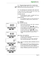
Page 23: ...on was run the shut off valve towards house installation must be initially kept closed In a next step forced regeneration should be carried out in order to drain the water fed trough the softener device directly to the canal 6 1 Operating the control valve for the first time Following the plugging in of the power adapter the time of day display on the control valve will flash Before executing any ...

Page 24: ...the control valve triggers the filling a few liters of water into the brine tank required for gen eration of the brine to be used by the next regeneration 6 3 Filling the brine tank with salt tablets Fill up the brine tank with salt tablets at least to a level that makes the residual water in the tank fully disappear filling up to the max capacity of the tank is harmless Please note The salt needs...

Page 25: ... an exter nal blending valve Since the blending valve integrated in the control valve works not very precisely when used with a low flow rate HygroMatik generally recommends the use of an external blending armature that works independant from pressure When such a valve is in use setting the mixed water hardness to zero is mandatory for correct determination of the residual capacity by the control ...

Page 26: ...g the NEXT key in the step described above pro gramming of the control valve was finished and the display returned to normal Time mode Changing the factory settings of further parameters Settings beyond the basic settings described here may be made by service personnel For that porpuse a dedicates program mining manual is available from Hygromatik 6 5 Setting of the optional external blending valv...

Page 27: ...GEN key with out any other effect Finishing an input step within a particular programming level will automatically make the control proceed to the next step in the order documented here 7 2 Overview on the display and operating options for the device operator normal operation Starting with the time of the day display on this level the user may only change the time setting view the current water fl...

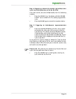
Page 28: ...s blinked Change the setting using the Δ and arrow keys Press the NEXT key for storage und to advance to the minutes setting the minutes field is blinked Change the setting using the Δ and arrow keys Press the SET CLOCK key again for storage and exi ting time of the day setting the display returns to TIME Step 2 View current water flow Starting fro TIME display press the NEXT key the cur rent wate...

Page 29: ... valve piston for execution of the first cycle defined The display will show REGEN and the corresponding cycle number starting with the first cycle and the cycle denomination Additionally the set cycle duration will be displayed and decreased as the cycle is executed At the start of a cycle the display is blinked for a few seconds After finishing a particular cycle the next cycle defined is auto m...

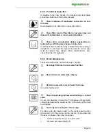
Page 30: ...ance once per year by an expert company for water treatment Warning When carrying out maintenance works pls keep in mind only expert staff may do the maintaining always obey security regulations Prior to maintenance work shut down operation of device and secure system against switching on pull power adap tor After finishing maintenance work have device checked for operational safety by expert pers...

Page 31: ...ust always be ensured Please note For hygienic reasons the following precautionary measures must be taken Store the regeneration salt exclusively in a dry and clean place Preferably do not use open packages or bags Clean the package or bag outside before opening it Fill the brine tank only directly with salt from the package or bag Under all circumstances close the brine tank carefully with the ca...

Page 32: ... cage must be cleaned see chapter Minor maintenance Also check brine tube for leakiness 8 2 3 Minor Maintenance These works should be carried out every 6 months Exchange filter insert in raw water fine filter Read and record water meter display Determine raw water and soft water hardness Use water hardness kit Check time of day and raw water setting on control valve In case of a deviation of more ...

Page 33: ... plug 5 Injector 6 Service spanner wrench Check leakiness of complete device including drain Check salt tablet supply in brine tank und fill up if required s Kap 8 2 1 Check salt consistency in brine tank The salt must not be agglutinated if required break up clumping with an appropriate tool or dissolve using hot water Check leakiness of brine tube and replace if required 1 2 3 4 5 l 1 6 ...

Page 34: ... salt Injector contaminated Clean injector and screen cage Salt consumption too high Brine FILL parameter wrongly set Correct FILL programming Contact expert company for drinking water treatment Loss of capacity Salt type inadequate Only use approved pure salt Raw water hardness has changed Check raw water hardness and cor rect control valve setting if required Brine concentration too low Allow sa...

Page 35: ...ressure tank Wash pressure tank with water and let dry Flush pipes and hoses with water and let dry Clean control valve with water and let dry Empty brine tank flush and let dry Let dry remaining salt and subsequently store in a dry place 9 2 Storage Store resin in moist condition protect against drying up Store resin frost free Store salt inventory and remaining salt from brine tank in a dry plac...

Page 36: ... aus folgenden Baugruppen T shape electrode bracket with brine tube inlet and brine tube outlet Control device Electrode cable with titan electrodes and connectors for control device connection Power adapter 10 2 Mounting the device Cut the brine tube at a suitable position Unscrew the two connecting nuts from the electrode bracket and push them onto the two brine tube endings that result from cut...

Page 37: ...ket The system is then in stand by The green power LED is on as long as the mains connection is not disrupted Three operating cycles may be distinguished see table below In case of a break of mains supply the current cycle will termi nate 10 5 Chlorine cell maintenance The electrode bracket should be disassembled approx every 6 months and be rinsed with warm water Any visible salt deposit must be ...

Page 38: ...cal specifications Control device Input voltage 12 VAC Output voltage 2 6 VDC 350 mA Protection class IP41 Power adapter Input voltage 230 VAC Output voltage 12 VAC Protection class IP 54 Conformity EC 23 73 and EC 336 89 ...

Page 39: ...rining kg 0 16 0 16 0 16 0 16 0 16 0 16 0 16 0 16 Water consumption per regeneration Liter 50 100 150 200 50 100 150 200 Dimensions weight and class Operational weight kg 110 125 135 145 125 140 150 160 Weight of device kg 24 29 33 38 40 47 55 63 Protection class IP Connections Electrical connection VAC Hz VA Min raw water flow pressure bar Max raw water flow pressure bar Min raw water temperature...

Page 40: ...6 0 16 0 16 0 16 0 16 0 16 Water consumption per regeneration Liter 250 400 500 600 750 1000 1300 120 Dimensions weight and class Operational weight kg 180 250 280 330 470 570 670 160 Weight of device kg 73 109 128 151 177 229 279 55 Protection class IP Connections Electrical connection VAC Hz VA Min raw water flow pressure bar 2 5 Max raw water flow pressure bar 7 Min raw water temperature C 5 Ma...

Page 41: ...750 1000 1200 1500 Dimensions weight and class Operational weight kg 190 250 320 360 560 660 830 1000 Weight of device kg 83 113 142 175 210 266 340 414 Protection class IP Connections Electrical connection VAC Hz VA Min raw water flow pressure bar 2 5 2 5 2 5 2 5 2 5 2 5 2 5 2 5 Max raw water flow pressure bar 7 7 7 7 7 7 7 7 Min raw water temperature C 5 5 5 5 5 5 5 5 Max raw water temperature C...

Page 42: ...000072 Mounting block 1 incl sampling cock differential pressure balance and blending valve 1 E 5000074 Pressure reducer R 1 with manometer 1 E 5000076 System separator BA R 1 DN25 incl connection fitting and discharge connection 1 E 5000086 Service spanner wrench 1 E 5000088 Free flow valve 1 with drain 1 E 5000040 Wastewater connection set according to DIN EN 1717 1 E 5000090 Funnel syphon white...

Page 43: ...Page 43 This page intentionally left blank ...

Page 44: ......

Reviews: