HydroTherm VSB2-605 Installation, Operation & Maintenance Manual And Replacement Parts List Download Page 12

tion unless there is lifting of  the flame above the burner
ports. If there is lifting, the air shutters should be gradu-
ally closed until the lifting is eliminated. It may also be
necessary to adjust the primary air shutters if the input
rate is reduced by a change in the orifices.

6. After burner has been in operation for about 10 min-
utes, check gas input rate to boiler as follows:

a. Make sure all appliances served by the meter are
turned off during timing of gas input rate to the boiler.

b. Measure the time in seconds that it takes for the
boiler to use 10 cubic feet of gas. Divide 36,000 by
the number of seconds (this is the number of cubic
feet of gas used per hour). Multiply this figure by the
heating value of the gas to obtain Btu input per hour. 

Example: A VS-110B boiler takes 5 minutes, 27 sec-
onds to use 10 cubic feet of natural gas. The local utility
indicated the heating value of the natural gas being sup-
plied is 1000 Btu/cu ft. Therefore: 

5 minutes, 27 seconds = 327 seconds.

36,000

X 1000  =  110,000 Btu/hr

327     

Therefore, the boiler input is correct.

NOTE: Before calculating the input of the heating
equipment, obtain the heating value of the gas from
the local utility.

7. If input needs to be corrected, adjust combination gas
valve pressure regulator. (Regulator is factory set at 3-
1/2" W.C. for natural gas and 10" W.C. for propane.)
Turn adjusting screw clockwise to increase gas flow
(increase input). Turn adjusting screw counterclockwise

to decrease gas flow (decrease input). In no case
should final manifold pressure setting vary more than +
.3" from factory-set pressures. If rated input cannot be
obtained with adjustment, gas supply pressure or orifice
size may be cause. Consult local utility and Hydrotherm.

8. Gas burner orifices supplied with boiler have been
carefully designed to provide correct gas input rate for
most gas conditions typically found in the U.S. Occa-
sionally, however, local gas characteristics may not allow
unit to be properly adjusted for input.  If this is the case,
local utility or Hydrotherm may recommend orifices be
changed.  When changing orifices follow the procedures
detailed in Section 4 of this manual.

9. Start and stop burners several times by raising and
lowering the thermostat setting.

10. After boiler has been firing long enough to raise boil-
er pressure above minimum setting of the primary pres-
suretol limit, check limit by turning its setting from maxi-
mum to minimum setting. This should turn boiler off.
Return limit to desired setting. 

11. Check boiler safety shutoff controls.

a. For boilers with standing pilot, with boiler firing, dis-
connect thermocouple lead from the valve. The valve
should close.

b. For boilers with intermittent pilot, with boiler firing,
disconnect wire connected to the "PV" terminal on the
Honeywell S8600 control. The gas valve should
close.

12. On initial start-up and prior to each heating season,
boiler must be cleaned with a commercially available
steam boiler cleaner (see "Steam Boiler Cleaning
Instructions" in Section 4 of this manual).

12

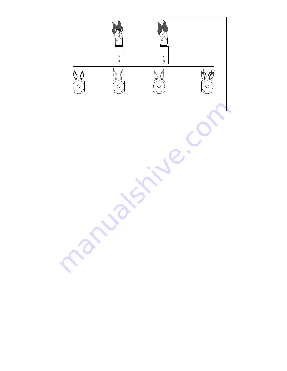
FIGURE 3.2: BURNER FLAME COMPARISON/PILOT FLAME

NORMAL

(HARD FLAME)

LIFTING

(TOO MUCH AIR)

YELLOW TIPPING

(MARGINAL)

YELLOW FLAME

(TOO LITTLE AIR)

NORMAL PILOT

FLAME

MAIN BURNER FLAMES

 Q314A/Q309A

CONSTANT PILOT

MODELS

 Q345

INTERMITTENT

IGNITION PILOT

MODELS

Summary of Contents for VSB2-605

Page 1: ...mpliance 2 Venting Requirements 2 Chimney Requirements 3 Combustion Air Requirements 3 Water Treatment 3 Shipment of Boiler 3 SECTION 2 BOILER INSTALLATION Step 1 Locating Setting Boiler 4 Step 2 Inst...

Page 2: ...ms operating under positive pressure When two or more appliances vent into a common flue the area of the common flue should be at least equal to the area of the largest flue plus 50 of the areas of th...

Page 3: ...e outside or through a vertical duct each opening must have a minimum free area of one square inch per 4000 Btu hr of gas input Horizontal ducts to the outside must have a minimum free area of one squ...

Page 4: ...ing rain etc during appliance operation and service low water cut off replacement condensate trap control replacement NOTE Do not loosen tie rods on boiler absorption unit They are intended to accommo...

Page 5: ...g to terminate within 6 of the floor Check local code requirements if in doubt Discharge piping must be of same size or larger than the relief valve outlet and should be run as short and straight as p...

Page 6: ...must be accessible for servicing and checking position indicator Remove hairpin shipping clip which holds damper blade in closed position and observe that damper blade rotates slowly to open position...

Page 7: ...w for servicing Check local codes and utilities for any special requirements and procedures Pipe joint compound pipe dope must be compatible with the fuel natural gas or propane being used FIGURE 2 6...

Page 8: ...1180 2205 80 89 185 346 724 1086 2047 90 83 173 322 677 1023 1921 100 78 162 307 630 967 1811 125 69 146 275 567 866 1606 150 63 132 252 511 787 1498 1 2 3 4 1 1 1 4 1 1 2 2 FIGURE 2 7 GAS PIPE SIZIN...

Page 9: ...nsulation may melt or degrade expos ing bare wire NOTE Boiler transformer must not be used to power external accessories i e zone valves relays etc Otherwise transformer will be overload ed and burn o...

Page 10: ...ENS 7 PILOT IS IGNITED AND SENSOR SENSES FLAME 9 UNIT OPERATES UNTIL THERMOSTAT OR OPERATING CONTROL IS SATISFIED FIELD WIRING FACTORY WIRING LOW WATER CUTOFF ARE ENERGIZED CONTROL SWITCH SPILL BLUE B...

Page 11: ...ION 1 Check combination gas valve on boiler and make sure it is in the OFF position 2 For vent damper equipped models with the thermo stat set to call for heat observe that vent damper posi tion indic...

Page 12: ...ng vary more than 3 from factory set pressures If rated input cannot be obtained with adjustment gas supply pressure or orifice size may be cause Consult local utility and Hydrotherm 8 Gas burner orif...

Page 13: ...electric power to the appliance 4 Remove control access panel if applicable 5 Rotate gas control knob clockwise to OFF 6 Wait five 5 minutes to clear out any gas Then smell for gas including near the...

Page 14: ...ith an ignition device which automatically lights the pilot Do not try to light the pilot by hand 5 Remove control access panel if applicable 6 Rotate gas control knob clockwise to OFF 7 Wait five 5 m...

Page 15: ...t off has been utilized follow the manufacturer s maintenance instructions As a minimum Inspect the probe and test the operation of electronic con trols at least once a year Remove clean and inspect t...

Page 16: ...ifices 3 Check orifices for proper drill size Size is stamped onto the body of the brass orifice see Figure 4 1 Size can also be checked by using a pin gauge 4 All orifices are screwed into the manifo...

Page 17: ...P BBR10 62 3327 1 1 1 1 15 Manifold 24 1411 1 Manifold 24 1413 1 1 Manifold 24 1414 1 16 Gas Valve 24 V Nat Gas 02 1543 1 1 1 1 VR8204 H 1006 Gas Valve 24 V L P Gas 02 1546 1 1 1 1 VR8204 H 1014 17 B...

Page 18: ...1026 1 1 1 1 38 Pressuretrol 02 4807 1 1 1 1 39 Tee 1 2 X 1 2 X 1 4 56 1351 1 1 1 1 40 Press Gauge 20 3002 1 1 1 1 41 Water Gauge 20 2005 1 1 1 1 42 Nipple 3 4 X 14 53 1136 1 1 1 1 43 Coupling 3 4 56...

Page 19: ...78 1 1 1 1 73 Nipple 1 2 X 3 Brass 53 1111 2 2 2 2 74 Nipple 1 2 X Close 53 1076 1 1 1 1 75 Nipple 1 2 X 3 53 1080 2 2 2 2 PARTS FOR VS B JACKET ASSEMBLY SEE FIGURE 3 Jacket Complete BM 2648 1 Jacket...

Page 20: ...2 3327 1 1 1 1 19 Thermocouple Q309A 04 1302 1 1 1 Thermocouple Q309A 3 FT 04 1306 1 20 Pilot Line w Fittings BM 8078 1 1 1 Pilot Line w Fitting BM 8079 1 22 Gas Valve NG VR8200H1129 02 1540 1 1 1 1 G...

Page 21: ...21 FIGURE 1 VS B GENERAL ASSEMBLY 45 43 26 21 20 19 24 33 29 44 15 14 6 12 10 7 17 13 5 42 30 22 16 11 8 9 27 28 23 31 27 28 25 4 1 3 2 18 65 66 32 41 39 35 36 37 38 40 34 46 77...

Page 22: ...N FIGURE 1 69 HONEYWELL RW700A LOW WATER CUT OFF AND FITTINGS McDONNELL MILLER 47 2 LOW WATER CUT OFF FEEDER AND FITTINGS 60 63 61 59 62 58 SAME AS IN FIGURE 1 FIGURE 2 LOW WATER CUT OFF AND FITTINGS...

Page 23: ...23 NOTES...

Page 24: ...260 NORTH ELM ST WESTFIELD MA 01085 413 564 5515 FAX 413 568 9613 5211 CREEKBANK ROAD MISSISSAUGA ONTARIO L4W 1R3 905 625 2991 FAX 905 625 6610...

Reviews: