Page 10
HV BOILER
INSTALLATION & OPERATING INSTRUCTIONS
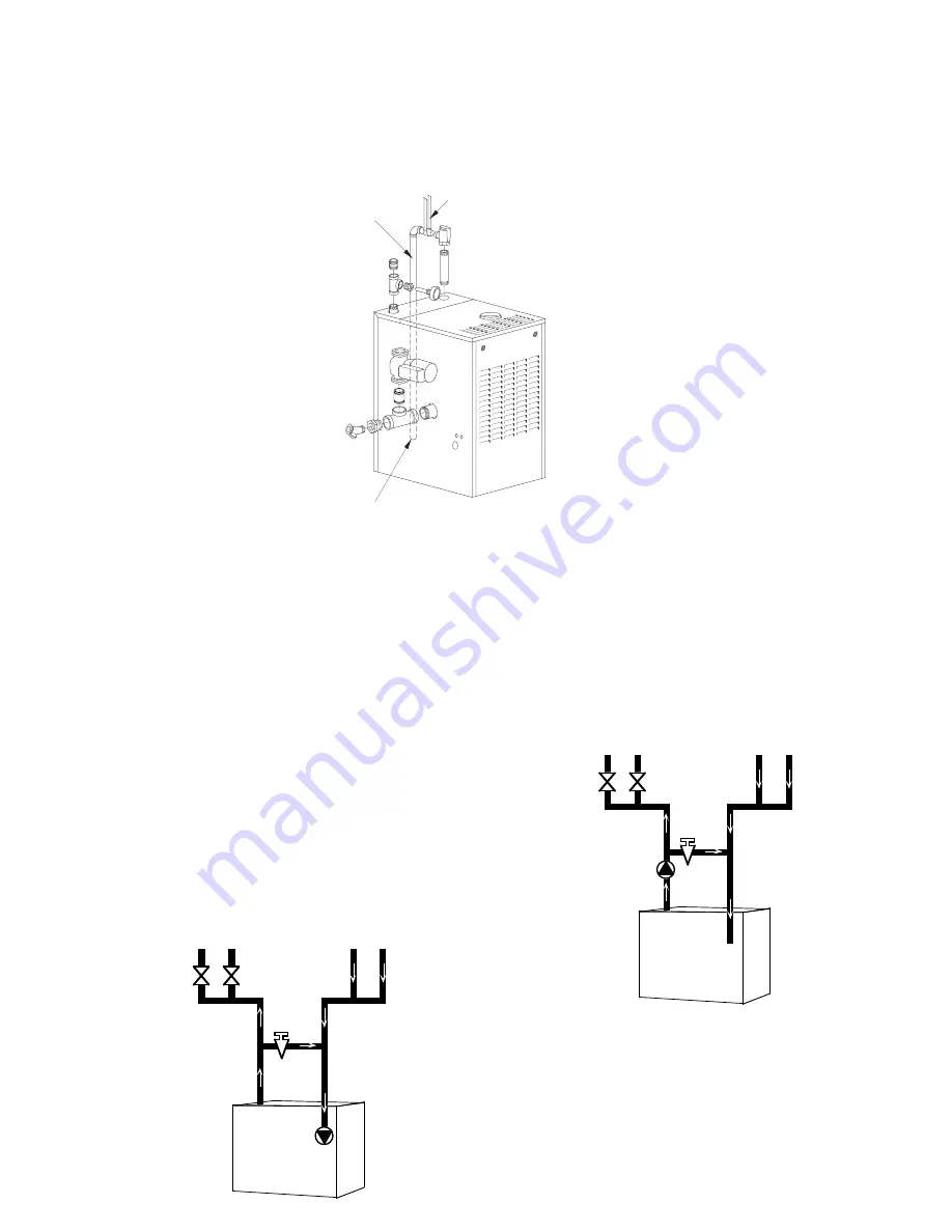
FIG. NO. 5 Heating System Piping
System Bypass
For systems using a circulator on the return as either a single
zone, or multiple zones with zone valves, install a system bypass
line between the supply and return on the suction side of the
circulator, see
FIG. NO. 6
. Install a metering valve in this bypass
line to regulate the amount of flow that will be diverted to the
return. A plug valve offers the best control for this application.
Although other valves may be less expensive, a plug valve will
be easier to set accurately.
In the absence of a flow indicator, set the metering valve using
temperature as a guide. The accompanying diagram suggests
one scenario. This addition requires only two tees, a plug valve,
and a small amount of pipe and offers the simplest approach to
reliably control condensation. For this system and those that
follow, be aware that you are using a percentage of the pump
capacity to blend, but the friction loss for the entire pump flow
has been reduced. In most cases, the standard pump packaged
with the boiler has enough capacity to feed the baseboard
distribution system and the bypass line.
FIG. NO. 6
Pump Away Bypass
For systems that use a single circulator to pump away from the
boiler, the bypass should be installed on the discharge side of
the circulator, see
FIG. NO. 7
. Full temperature water supplies
the baseboard distribution system as before. Half of the
circulator’s volume moves through the bypass, blending and
heating the cooler return water. Again, the cost of installing the
bypass is small and setting it by temperature can be
accomplished with a contact thermometer.
FIG. NO. 7
SUPPLY
RETURN
50%
120° F
100%
140° F
100%
160° F
50%
160° F
50%
160° F
SYSTEM
BYPASS
SUPPLY
RETURN
50%
120° F
100%
140° F
100%
160° F
50%
160° F
50%
160° F
PUMP AWAY
BYPASS
1" CLEARANCE MU
S
T BE
MAINTAINED BETWEEN
HOT WATER PIPING
AND COMBU
S
TIBLE
CON
S
TRUCTION.
DI
S
CHARGE PIPE
S
IZE TO EQUAL
VALVE OUTLET.
DO NOT RE
S
TRICT
FLOW.
S
UPPORT DI
S
CHARGE PIPING
S
O A
S
TO AVOID
S
TRAIN ON
THE VALVE BODY.
DI
S
CHARGE
S
O A
S
TO AVOID EXPO
S
URE OF PER
S
ON
S
TO
HOT LIQUID OR VAPOR. L E A V E O P E N E N D V I
S
I B L E F O R
P E R I O D I C IN
S
PECTION FOR
S
LOW LEAKAGE OR DRIP
S
.
FOR DI
S
CHARGE
THROUGH ROOF
CON
S
ULT
HYDROTHERM.


