background image

Hydro

Tab

Marine Engineering

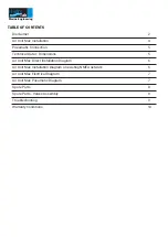
TABLE OF CONTENTS

Disclaimer

2

Air Unit Max Installation

4

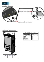
Pneumatic Connection

5

Technical Data + Dimensions

5

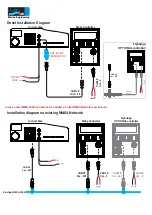
Air Unit Max Direct Installation Diagram

6

Air Unit Max Installation Diagram on existing NMEA network

6

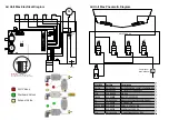
Air Unit Max Electrical Diagram

7

Air Unit Max Pneumatic Diagram

7

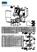
Spare Parts

8

Spare Parts - Valves Assembly

8

Troubleshooting

9

Warranty Conditions

10

Summary of Contents for AIR UNIT MAX

Page 1: ...Hydro Tab Marine Engineering Hydrotab BT Series INSTALLATION MANUAL AIR UNIT MAX NMEA 2000 NMEA 0183 Hydro Tab Marine Engineering...

Page 2: ...n patents pending Declaration of conformity This product conforms to the following Electromagnetic Compatibility EMC regulations and standards for use in marine environments CE EN 60945 Technical info...

Page 3: ...Connection 5 Technical Data Dimensions 5 Air Unit Max Direct Installation Diagram 6 Air Unit Max Installation Diagram on existing NMEA network 6 Air Unit Max Electrical Diagram 7 Air Unit Max Pneumat...

Page 4: ...ING FREE OF EXPLOSIVE OR FLAMMABLE GASES THE AIR UNIT MUST BE INSTALLED IN A COMPARTMENT THE AIR UNIT MUST BE INSTALLED 20cm BELOW ANY SURFACE THAT LOCATES ABOVE IT WARNING 1 2 444mm Drill 3 You will...

Page 5: ...and connect it to the Air Unit Hydro Tab Marine Engineering Technical Data Dimensions A 259 mm B 143 mm C 459 mm Compressor power 380 W Air compressor type Brushless oil free Voltage 24 V Amps 15 A In...

Page 6: ...A 2000 Flybridge OPTIONAL controller CABLE 3m MF Moby Controller Direct Installation Diagram CABLE 10m FF In case a new NMEA 2000 instrument to be added a proper NMEA Network must be built USE INLINE...

Page 7: ...4V 12 24V NMEA 2000 T1 M Compressor 500 AIR N2 V2 1 F1 F1 3A 24V DC 230V DC 24V DC 230V DC 24V DC 230V DC C5 Timer Switch 12V Tr1 1 2 3 4 LEFT RIGHT 1 2 3 4 LEFT RIGHT SYMBOL Part No Description C1 C4...

Page 8: ...1 PNE 01242C FILTER 1 36 RUB 00162 PCB RUBBER BASE 1 37 RUB 00163 VENTOURI RUBBER SUPPORT 1 44 ELE 00057 CABLE GLAND PG13 5 1 Valves Assembly see below Spare Parts Valves Assembly 54 53 55 50 52 56 51...

Page 9: ...mper wire between COM and LDRU RDLU DN UP Do you notice relevant red lights on 1 Reset or replace the fuses 2 Check the wires which are connected to PCB and transformer 3 Replace the transformer When...

Page 10: ...tab gr product registration In case the dealer sells separate units of Interceptors Air Units and Controllers that constitute a full system that is not initially sold as a complete system by Hydrotab...

Page 11: ...Hydro Tab Marine Engineering Notes...

Page 12: ...Hydro Tab Marine Engineering 4 Papazoglou str GR 17778 Athens Greece email info hydrotab gr website www hydrotab gr REV C Hydro Tab Marine Engineering...

Reviews: