


INSTALLATION
Hazardous voltage. Can shock, burn or kill.
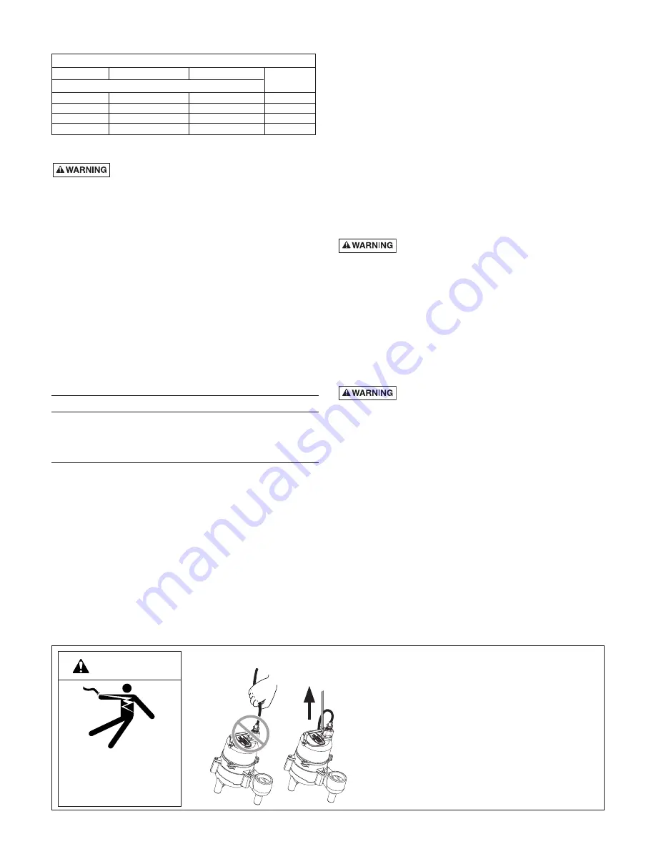
Do not lift pump by the power cord. See “Cord Lift Warning”
below.
NOTICE:
Install the pump on a hard, level surface (cement,
asphalt, etc.). Never place the pump directly on earth, clay or
gravel surfaces. Install the pump in a sump basin with a
minimum diameter of 18" (46cm).
Piping
Piping must not be smaller than pump discharge.
When installed in a
sewage
system, the pipe must be
capable of handling semi-solids of at least
2"
(51mm) in
diameter.
When installed in an
effluent
system, the pipe must be
capable of handling semi-solids of at least
3/4"
(19mm) in
diameter.
The rate of flow in the discharge pipe must keep any solids
present in suspension in the fluid. To meet minimum flow
requirements (2 feet per second in the discharge line), size
the pipe as follows:
A Pipe Size Of:
Will Handle a Flow Rate Of:
1-1/2" (38mm)
12 GPM
2" (51mm)
21 GPM
2-1/2"(64mm)
30 GPM
3"(76mm)
48 GPM
In a
sewage
system use a
2"
(51mm) check valve in pump
discharge to prevent backflow of liquid into sump basin. The
check valve should be installed 12–18" (317–457mm) above the
pump discharge and be a free flow valve that will easily pass
solids. Be sure check valve installation complies with local codes.
In an effluent system use a
1-1/2"
(28mm) check valve in pump
discharge to prevent backflow of liquid into sump basin.
NOTICE:
For best performance of check valve when handling
solids, do not install it with the discharge more than 45° above
the horizontal. Do not install the check valve in a vertical
position as solids may settle in the valve and prevent it from
opening on startup.
Drill a 3/16" (5mm) hole in the discharge pipe about 1–2"
(25-51mm) above the pump discharge connection (but below
check valve) to prevent airlocking the pump.
Be sure that the wide-angle float switch hangs freely. It should
not be able to come in contact with the sides or bottom of the
sump pit.
Make sure the sump pit is free of any debris that could
obstruct the intake volute or switch.
Use plumbing materials that are approved by local building
codes when connecting pipes between pump and sewer
outlet.
NOTICE:
For critical indoor installations where additional
high water protection is desired, install a “Q-Alert” audible
alarm system in the sump pit. For outdoor installations,
confer with your Hydromatic distributor.
Connect the power cord to a 3-prong grounded AC
receptacle.
Hazardous voltage. Can shock, burn or kill.
DO NOT remove the grounding pin from the power cord.
Avoid using extension cords or 2-prong adapter plugs.
Insert the piggyback plug that comes from the wide-angle
float switch directly into the power receptacle.
Insert the pump power cord directly into the back of the
piggyback plug.
Test the pump installation by filling the sump basin with
enough water to activate the pump and repeat this cycle until
satisfied with pump operation.
Electrical
Hazardous voltage. Can shock, burn, or kill.
When installing, operating, or servicing this pump, follow the
safety instructions listed below.
1.
DO NOT
splice the electrical power cord.
2.
DO NOT
allow the plug on the end of the electrical cord
to be submerged.
3.
DO NOT
use extension cords. They are a fire hazard and
can reduce voltage sufficiently to prevent pumping and/or
damage motor.
4.
DO NOT
handle or service the pump while it is
connected to the power supply.
5.
DO NOT
remove the grounding prong from the plug or
modify the plug. To protect against electrical shock, the
power cord is a three-wire conductor and includes a 3-
prong grounded plug. Plug the pump into a 3-wire,
grounded, grounding-type receptacle. Connect the pump
according to the NEC or CEC and local codes.
For automatic operation, plug the pump into the piggy-back
switch plug. Plug the piggy-back switch plug into the outlet.
For continuous running, plug the pump directly into the outlet
(that is, bypass the piggyback switch plug).
2
1. Attempting to lift or support pump by power cord
can damage cord and cord connections.
2. Cord may pull apart, exposing bare wires with
possibility of fire or electrical shock.
3. Lifting or supporting pump by power cord will
void warranty.
4. Use lifting ring or handle on top of pump for all
lifting/lowering of pump. Disconnect power to
pump before doing any work on pump or
attempting to remove pump from sump.
Risk of electrical shock.
Can burn or kill.
Do not lift pump by
power cord.
WARNING
CORD LIFT WARNING
PERFORMANCE
GPM AT TOTAL FEET
Model
10
15
CAPACITY GALLONS/MINUTE
SKV40M1
78
40
19
SKV40A1
78
40
19
SKV40M2
78
40
19
SKV40A2
78
40
19
No flow
at height
shown below
Summary of Contents for SKV40
Page 8: ......