25
6.2.7
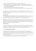
Symbol of automatic stop, the light will be on when it is in operation.
Note: When parameter P6 is on checking/adjusting, Symbol of automatic stop light
will be flash.
6.2.8
Symbol of automatic start, the light will be on when it is in operation.
Note: When parameter P5 is on checking/adjusting, Symbol of automatic start light
will be flash.
6.2.9
Press this button, the light will be flash,
the heat pump will operate in ‘Full output’ only.
6.2.10
While you choose the Smart, the heat pump will just operate in ‘Small output’ , ‘Medium output’ and ‘Full
output’
When in ‘Small output’, the lamp of Smart is lighting, the light of Silent will be flash.
When in ‘Medium output’, the light of Smart will flash.
When in ‘Full output’, the lamp of Smart is lighting, the lamp of Powerful will be flash.
6.2.11
While you choose the Silent , the heat pump will just operate in ‘Medium output’ and ‘Small output’
When in ‘Small output’, the light of Silent will flash.
When in ‘Medium output’, the lamp of Silent is lighting, the lamp of Smart will be flash
Summary of Contents for 7024515
Page 12: ...10 2 Dimension mm Model Z7 32 Model Z11 32 Z14 32 Z16 32 ...
Page 13: ...11 Model Z19 32 Model Z24 32 Z24T Z29 32 Z29T ...
Page 21: ...19 5 2 SWIMMING POOL HEAT PUMP WIRING DIADRAM Z24 32 ...
Page 22: ...20 5 3 SWIMMING POOL HEAT PUMP WIRING DIADRAM Z29 32 ...
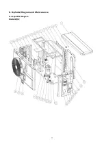
Page 35: ...33 8 Exploded Diagram and Maintenance 8 1 Exploded Diagram Model Z7 32 ...
Page 36: ...34 ...
Page 38: ...36 Model Z24 32 ...
Page 39: ...37 ...
Page 48: ...46 2 Dimension Model Z7 32 Model Z11 32 Z14 32 Z16 32 ...
Page 49: ...47 Model Z19 32 Model Z24 32 Z24T Z29 32 Z29T ...
Page 57: ...55 5 2 SCHEMA DE CABLAGE DE POMPE À CHALEUR DE PISCINE Z24 32 ...
Page 58: ...56 5 3 SCHEMA DE CABLAGE DE LA POMPE À CHALEUR DE PISCINE Z29 32 ...
Page 72: ...70 8 Schéma eclaté et entretien 8 1 Schéma eclaté Model Z7 32 ...
Page 73: ...71 ...
Page 75: ...73 Model Z24 32 ...
Page 76: ...74 ...
Page 85: ...83 2 Afmeting Dimension Model Z7 32 Model Z11 32 Z14 32 Z16 32 ...
Page 86: ...84 Model Z19 32 Model Z24 32 Z24T Z29 32 Z29T ...
Page 94: ...92 5 2 ZWEMBAD WARMTEPOMP BEDRADING SCHEMA Z24 32 ...
Page 95: ...93 5 3 ZWEMBAD WARMTEPOMP BEDRADING SCHEMA Z29 32 ...
Page 109: ...107 8 Open geklapt diagram en onderhoud 8 1 Open geklapt diagram Model Z7 32 ...
Page 110: ...108 ...
Page 112: ...110 Model Z24 32 ...
Page 113: ...111 ...
Page 122: ...120 2 Ausmaße Model Z7 32 Model Z11 32 Z14 32 Z16 32 ...
Page 123: ...121 Model Z19 32 Model Z24 32 Z24T Z29 32 Z29T ...
Page 130: ...128 5 1 VERKABELUNGSDIAGRAMM DER SCHWIMMBECKEN WÄRMEPUMPE Z7 32 Z11 32 Z14 32 Z16 32 Z19 32 ...
Page 131: ...129 5 2 VERKABELUNGSDIAGRAMM DER SCHWIMMBECKEN WÄRMEPUMPE Z24 32 ...
Page 132: ...130 5 3 VERKABELUNGSDIAGRAMM DER SCHWIMMBECKEN WÄRMEPUMPE Z29 32 ...
Page 146: ...144 8 Explosionszeichnung und Wartung 8 1 Explosionszeichnung Model Z7 32 ...
Page 147: ...145 ...
Page 149: ...147 Model Z24 32 ...
Page 150: ...148 ...
Page 159: ...157 2 Wymiary Model Z7 32 Model Z11 32 Z14 32 Z16 32 ...
Page 160: ...158 Model Z19 32 Model Z24 32 Z24T Z29 32 Z29T ...
Page 168: ...166 5 2 SCHEMAT OKABLOWANIA POMPY GRZEWCZEJ DO BASENOW KĄPIELOWYCH Z24 32 ...
Page 169: ...167 5 3 SCHEMAT OKABLOWANIA POMPY GRZEWCZEJ DO BASENOW KĄPIELOWYCH Z29 32 ...
Page 183: ...181 8 Schemat budowy pompy 8 1 Widok urządzenia rozebranego Model Z7 32 ...
Page 184: ...182 ...
Page 186: ...184 Model Z24 32 ...
Page 187: ...185 ...
Page 196: ...194 2 Dimension mm Model Z7 32 Model Z11 32 Z14 32 Z16 32 ...
Page 197: ...195 Model Z19 32 Model Z24 32 Z24T Z29 32 Z29T ...
Page 205: ...203 5 2 SWIMMINGPOOL VARMEPUMPE WIRING DIAGRAM Z24 32 ...
Page 206: ...204 5 3 SWIMMINGPOOL VARMEPUMPE WIRING DIAGRAM Z29 32 ...
Page 220: ...218 8 Eksploderede Diagram og vedligeholdelse 8 1 Eksploderede Diagram Model Z7 32 ...
Page 221: ...219 ...
Page 223: ...221 Model Z24 32 ...
Page 224: ...222 ...
Page 230: ...228 A0111HYIR3201 ...


