22
5.5 Installation of the display deportee
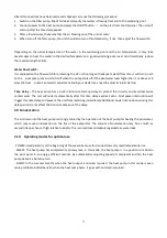
Photo(1)
Photo(2) Photo(3) Photo(4) Photo(5)
- The side with plug connects with the control panel (photo1)
- The other side of the signal wire. (photo2)
- Open the wiring panel and put the side without plug through the electrical box. (photo3,4)
- Insert the wiring into the disignated position (
code:COM 1 or COM-L)
on the PC board. (photo5)
6. Display Controller Operation
6.1
The buttons of LED wire controller
6.2 The keys and their operations
NOTE: Every time, when the heat pump connects to the power, the LED display shows a code for 3 seconds which
indicates the heat pump model.
Model
Z7/32
Z11/32
Z14/32
Z16/32
Z19/32
Z24/32
Z24T
Z29/32
Z29T
Code
1302
1304
1305
1306
1308
1311
1519
1312
1520
6.2.1
button
Press
to start the heat pump unit, the LED display shows the desired water temperature for 5 seconds, then
shows the inlet water temperature and the operation mode.
Press
to stop the heat pump unit and show “OFF”
Summary of Contents for 7024515
Page 12: ...10 2 Dimension mm Model Z7 32 Model Z11 32 Z14 32 Z16 32 ...
Page 13: ...11 Model Z19 32 Model Z24 32 Z24T Z29 32 Z29T ...
Page 21: ...19 5 2 SWIMMING POOL HEAT PUMP WIRING DIADRAM Z24 32 ...
Page 22: ...20 5 3 SWIMMING POOL HEAT PUMP WIRING DIADRAM Z29 32 ...
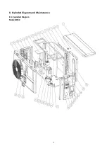
Page 35: ...33 8 Exploded Diagram and Maintenance 8 1 Exploded Diagram Model Z7 32 ...
Page 36: ...34 ...
Page 38: ...36 Model Z24 32 ...
Page 39: ...37 ...
Page 48: ...46 2 Dimension Model Z7 32 Model Z11 32 Z14 32 Z16 32 ...
Page 49: ...47 Model Z19 32 Model Z24 32 Z24T Z29 32 Z29T ...
Page 57: ...55 5 2 SCHEMA DE CABLAGE DE POMPE À CHALEUR DE PISCINE Z24 32 ...
Page 58: ...56 5 3 SCHEMA DE CABLAGE DE LA POMPE À CHALEUR DE PISCINE Z29 32 ...
Page 72: ...70 8 Schéma eclaté et entretien 8 1 Schéma eclaté Model Z7 32 ...
Page 73: ...71 ...
Page 75: ...73 Model Z24 32 ...
Page 76: ...74 ...
Page 85: ...83 2 Afmeting Dimension Model Z7 32 Model Z11 32 Z14 32 Z16 32 ...
Page 86: ...84 Model Z19 32 Model Z24 32 Z24T Z29 32 Z29T ...
Page 94: ...92 5 2 ZWEMBAD WARMTEPOMP BEDRADING SCHEMA Z24 32 ...
Page 95: ...93 5 3 ZWEMBAD WARMTEPOMP BEDRADING SCHEMA Z29 32 ...
Page 109: ...107 8 Open geklapt diagram en onderhoud 8 1 Open geklapt diagram Model Z7 32 ...
Page 110: ...108 ...
Page 112: ...110 Model Z24 32 ...
Page 113: ...111 ...
Page 122: ...120 2 Ausmaße Model Z7 32 Model Z11 32 Z14 32 Z16 32 ...
Page 123: ...121 Model Z19 32 Model Z24 32 Z24T Z29 32 Z29T ...
Page 130: ...128 5 1 VERKABELUNGSDIAGRAMM DER SCHWIMMBECKEN WÄRMEPUMPE Z7 32 Z11 32 Z14 32 Z16 32 Z19 32 ...
Page 131: ...129 5 2 VERKABELUNGSDIAGRAMM DER SCHWIMMBECKEN WÄRMEPUMPE Z24 32 ...
Page 132: ...130 5 3 VERKABELUNGSDIAGRAMM DER SCHWIMMBECKEN WÄRMEPUMPE Z29 32 ...
Page 146: ...144 8 Explosionszeichnung und Wartung 8 1 Explosionszeichnung Model Z7 32 ...
Page 147: ...145 ...
Page 149: ...147 Model Z24 32 ...
Page 150: ...148 ...
Page 159: ...157 2 Wymiary Model Z7 32 Model Z11 32 Z14 32 Z16 32 ...
Page 160: ...158 Model Z19 32 Model Z24 32 Z24T Z29 32 Z29T ...
Page 168: ...166 5 2 SCHEMAT OKABLOWANIA POMPY GRZEWCZEJ DO BASENOW KĄPIELOWYCH Z24 32 ...
Page 169: ...167 5 3 SCHEMAT OKABLOWANIA POMPY GRZEWCZEJ DO BASENOW KĄPIELOWYCH Z29 32 ...
Page 183: ...181 8 Schemat budowy pompy 8 1 Widok urządzenia rozebranego Model Z7 32 ...
Page 184: ...182 ...
Page 186: ...184 Model Z24 32 ...
Page 187: ...185 ...
Page 196: ...194 2 Dimension mm Model Z7 32 Model Z11 32 Z14 32 Z16 32 ...
Page 197: ...195 Model Z19 32 Model Z24 32 Z24T Z29 32 Z29T ...
Page 205: ...203 5 2 SWIMMINGPOOL VARMEPUMPE WIRING DIAGRAM Z24 32 ...
Page 206: ...204 5 3 SWIMMINGPOOL VARMEPUMPE WIRING DIAGRAM Z29 32 ...
Page 220: ...218 8 Eksploderede Diagram og vedligeholdelse 8 1 Eksploderede Diagram Model Z7 32 ...
Page 221: ...219 ...
Page 223: ...221 Model Z24 32 ...
Page 224: ...222 ...
Page 230: ...228 A0111HYIR3201 ...


