ZT-2800
®
/ZT-3100/ZT-3400™
33
BraKe asseMBLY (Code 3)
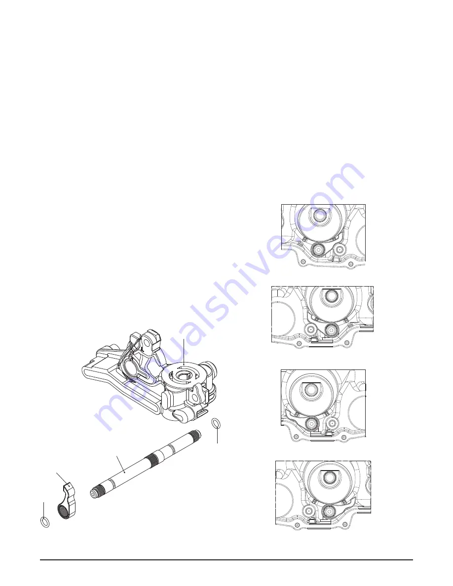
Refer to Figure 28
disassembly
1. Remove the center section per detail on
page 31.
NOTE:
Take note of the orientation of the brake
pawl (100) and the brake shaft (101).
2. Remove the brake shaft (101) and the brake
pawl (100).
3. Remove the O-rings (10) from the brake
shaft (101) and discard the O-rings.
4. Remove the brake pawl from the brake shaft
if pawl, shaft or splines are damaged.
inspection
1. Inspect all components for unusual wear or
damage.
assembly
1. If removed, install brake pawl on brake shaft.
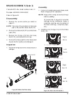
Refer to figure 29 for orientation
NOTE:
Apply a thin coating of oil to the O-rings
before installing.
To protect the O-rings from possible
damage during installation, apply a
protective covering over the splines of
the brake shaft (e.g., cellophane, tape,
etc.).
2. Install the new O-rings (10) onto the brake
shaft (101).
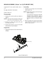
figure 28, Brake shaft assembly
Z * - (G, H, J) * * * - * (A-D, J-M) * * - * * * *
Z * - (K, L, M) * * * - * (E-H, N-T) * * - * * * *
figure 29, Brake pawl Orientation
Z * - (G, H, J) * * * - * (E-H, N-T) * * - * * * *
Z * - (K, L, M) * * * * - * (A-D, J-M) * * - * * * *
Character #7 in the model number code = 3
Example: ZX-XXXX-3XXX-XXXX
Right
Rot. A
Left
Rot. A
Right
Rot. B
Left
Rot. B
100
101
10
10
Center Section

