14
5. Connection of Vacuum Hoses:
The vacuum connection on the machine can be either a 2” hose barb or 2” male Flash Cuff. Both are
included with your MX3-1200JP. The desired connector can be threaded into the vacuum port on the front
of the machine.
A 2” female Flash Cuff 1-1/2” hose adapter is also included to connect the 1-1/2” vacuum hose to the 2”
male Flash Cuff on the machine.
A 2” hose cuff for 1-1/2” vacuum hose is included to connect the 1-1/2” vacuum hose to the 2” hose barb
on the machine.
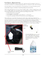
There are three components used to connect the cleaning tool to the vacuums and recovery tank:
1.
A short 4’ vacuum hose: Connect one end to the 2” vacuum barb or 2” male Flash Cuff to the front
of the machine using the appropriate cuff and the other to the outlet side of the Hydro Filter.
2.
A Hydro Filter II inline filter.
3.
A 25’ Vacuum Hose: The 2” cuff on the 25’ vacuum hose is connected to the inlet side of the hydro
filter. The other end with the 1-1/2” cuff is connected to the cleaning tool.
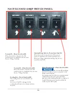
When ready to begin cleaning, turn both vacuum switches to the ON position. If connected in series, the
MX3-1200JP can be operated with only one vacuum for cleaning delicate fabrics. (See Vacuum Connection
instructions on Page 8) In most situations you will turn both vacuum switches ON.
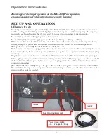
Hydro-Filter II – AC10
Short Vacuum Hose
1-1/2” x 4’ with 2” Cuff & 2” female Flash Cuff adapter
Vacuum Hose
1-1/2” x 25’ with 2” & 1-1/2” cuffs
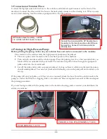
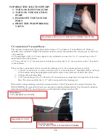
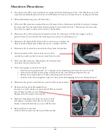
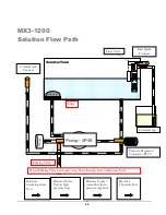
TO PRIME THE SOLUTION PUMP:
1.
TURN ON BOTH VACUUMS
2.
TURN ON THE SOLUTION
PUMP
3.
BLOCK OFF THE VACUUM
PORT
4.
PRESS THE PUMP PRIMING
VALVE
BLOCKING THE VACUUM PORT TO PRIME THE PUMP
Summary of Contents for Nautilus MX3-1200JP
Page 1: ...1 LMANN19 Revised 01 29 2015 Nautilus MX3 1200JP Operating Manual ...
Page 39: ...39 NM5740 AUTO FILL FLOAT VALVE ASSEMBLY ...
Page 41: ...41 Pump Out Pump AP37 PARTS ASSEMBLY ...
Page 42: ...42 1 2 3 5 4 4 6 7 8 9 10 8 9 3 8 9 8 9 23 100 104 12 11 2 39 ...
Page 49: ...49 2 39 1 72 73 73 67 9 30 31 82 83 2 83 82 84 INSIDE SOLUTION TANK BOTTOM VIEW SOLUTION TANK ...
Page 51: ...51 PUMP OUT CONNECTIONS 96 88 112 105 93 99 96 91 95 97 9 111 113 117 119 ...
Page 52: ...52 FLOW 81 92 91 99 96 9 97 105 13 14A 14 95 PUMP OUT PARTS 1 39 9 97 119 ...


