background image

   Machine Maintenance:  5-4

OVERALL MACHINE MAINTENANCE

Maintenance, troubleshooting and repair are much easier tasks to accomplish on a clean 

truckmount. Regular cleaning of the truckmount offers the user an opportunity to visually 

inspect all facets of the truckmount and spot potential problems before they occur. In 

addition to the operational maintenance the following “housekeeping” duties should be 

performed.

After each job

• 

Check the recovery tank and the recovery tank filters. Empty and clean as necessary.

Daily

•  Wipe the truckmount down thoroughly with a damp cloth. 

•  Wipe down the vacuum and high pressure hoses as needed.

•  Inspect and clean the vacuum slot on the cleaning wand.

•  Check the wand head for sharp edges that could tear carpet. File down as needed.

•  Clean the wand to maintain original appearance.

•  Visually inspect the hoses for abrasions, cuts, etc. Repair or replace as needed.

Weekly

•  Empty the chemical container. Wash out thoroughly to remove any chemical buildup.

•  Inspect the chemical feed line strainer and use solution of equal parts white vinegar 

and water to remove any chemical buildup.

•  Thoroughly clean the wand and inspect for clogged jets, debris in vacuum slot and 

leaking fittings at valve.

•  Thoroughly clean the vacuum and high pressure hoses including quick releases and 

cuffs.

Summary of Contents for Truckmount to Go TMTG 4000

Page 1: ...this manual may be reproduced or used in any form or by any means i e graphic electronic photocopying or electronic retrieval systems without the express written permission of HydraMaster Specifications and information in this document are subject to change without prior notice All rights reserved 2019 HydraMaster ...

Page 2: ......

Page 3: ... for Extraction 3 2 Rinse and Recover 3 2 Overwetting 3 3 Streaking 3 3 Cleaning Tool Tips 3 4 OPERATING INSTRUCTIONS SECTION 4 Start Up Procedure 4 3 Shut Down Procedure 4 5 MACHINE MAINTENANCE SECTION 5 Operational Maintenance 5 2 Overall Machine Maintenance 5 4 Engine Maintenance 5 5 High Pressure Pump Maintenance 5 7 Vacuum System Maintenance 5 11 Descaling Procedure Required 5 12 Freeze Guard...

Page 4: ...er Assembly Parts List 9 33 Water Box Assembly Parts List 9 35 Exhaust Assembly Parts List 9 36 70 Gallon Universal Recovery Tank URT Assembly Parts List 9 38 70 Gallon Universal Recovery Tank URT Cover Assembly Parts List 9 40 14 Hose Reel Garden Assembly Parts List 9 41 Vacuum Relief Valve Assembly Parts List 9 42 Dump Vacuum Bracket TMTG Assembly Parts List 9 43 HOW TO ORDER PARTS SECTION 10 Wa...

Page 5: ...iii TMTG 4000 Owner s Manual ...

Page 6: ... that records of maintenance must be kept and copies may be required to be furnished to HydraMaster before any warranty is honored The Owner s Manual contains information on everything from cleaning and chemicals to truckmount operation and maintenance It also contains detailed machine assemblies and parts lists as well as a troubleshooting guide You should become familiar with the material in the...

Page 7: ...ies System Concept Machine Specifications High Altitude Operation Local Water Precautions Filling the fuel tank Securing the Load Operating Instructions Machine Maintenance Water and Chemical System Electrical System Systems Troubleshooting Assemblies and Parts List How to Order Parts Warranty Information Accessories and Chemical Solution ...

Page 8: ...g the following phone numbers HOURS TELEPHONE NUMBERS E MAIL ADDRESSES Monday Friday 7 00 a m to 5 00 p m Pacific Time Technical Support 800 426 1301 FAX 800 426 4225 Technical Support techsupport hydramaster com Customer Service Parts 800 426 1301 FAX 800 426 4225 Customer Service Parts parts hydramaster com When calling your distributor be sure to reference the serial number and date of purchase...

Page 9: ...ses this WARNING symbol throughout the manual to warn of possible injury or death This CAUTION symbol is used to warn of possible equipment damage This NOTICE symbol indicates that federal or state regulatory laws may apply and also emphasizes supplemental information ...

Page 10: ...e operation of the truckmount carbon monoxide and other toxic fumes are produced Position the vehicle so that any fumes produced will be directed away from inhabited areas and any points of building entry doors windows air conditioning units fans etc Do not occupy the vehicle while the truckmount is in operation Serious injury may result During the operation of the truckmount chemicals known to th...

Page 11: ...orm cleaning operations when the truckmount engine is running at the IDLE throttle position Failure to do so will increase the risk of serious component or engine damage Never operate the truckmount with the vehicle doors closed Doing so results in extremely high temperatures inside the vehicle and will lead to serious component or engine damage Never use concentrated acids or solvents including d...

Page 12: ...ng or otherwise removing wax from floors is specifically excluded as an approved use of the truckmount Failure to follow this exclusion may lead to component failure and will invalidate your warranty Use of the vacuum recovery system for dry cleaning without corresponding solution application i e duct cleaning is specifically excluded as an approved use of the truckmount Failure to follow this exc...

Page 13: ...ws and regulations must be followed for properly securing payloads Prior to operating the truckmount read this manual in its entirety and familiarize yourself with the information contained here Special attention should be paid to all cautions and warnings The distributor should provide a thorough review of the operation manual with the purchaser along with instruction and familiarization in How a...

Page 14: ...ent 2 Check the packing list and verify that all items are accounted for Installation Responsibilities Ensure proper payload capacity It is the distributor s responsibility to verify that the equipment package does not exceed the vehicle capacity Ensure proper placement of the truckmount fresh water tank and accessories in the vehicle and check that they are secured properly Check the pump vacuum ...

Page 15: ...t and shut down the truckmount 4 How to correctly clean with the truckmount 5 Where and how often to check and change component oil levels 6 Freezing damage and how to avoid it This includes explaining proper freeze guarding procedures 7 How to do basic troubleshooting of the truckmount 8 Hard water damage and how to avoid it This includes how to determine if hard water exists in your area and the...

Page 16: ... through college and industrial campuses amusement parks golf courses and resorts The HydraMaster Truckmount to Go is a mobile high performance cleaning and extrac tion system designed for restoration and cleaning contractors facility managers and disaster emergency response teams who need an easy to operate and easy to transport unit It can be directly delivered to the job site for immediate and ...

Page 17: ... into the transport vehicle for delivery to the job site or shipped by container or crate to the work site HydraMaster is one of the largest manufacturers of truck mounted and high perfor mance portable cleaning and extraction machines For over 48 years HydraMaster has innovated uncompromising deep cleaning extraction and drying solutions ...

Page 18: ... Fuel Consumption 1 1 GPH Ignition Electric Key Start 12 Volt Vacuum Blower Tuthill 4005 Competitor Plus SL Dual Splash Lubrication Max Vac 14 Hg Oil Type PneuLube or other ISO 100 rating Gear End Capacity Approx 5 8 oz Drive End Capacity Approx 4 7 oz Water Pump Oil Type 30w Non Detergent Electric Clutch Capacity Approx 8 oz Pump Flow Rate 3 5 GPM Pump RPM 1750 Operating Pressure 1 000 psi Chemic...

Page 19: ...Hose Connection Panel Vacuum AWDS and recovery tank drain Garden Hose Reel Non Live Includes 50 Garden hose w Reel Capacity up to 100 Solution Hose Reel Non Live Includes 100 Solution hose w Reel Capacity up to 250 Fuel Tank 7 Gallon Painted Steel EPA CARB SORE Approved 12vdc Battery YTX Van Decal Owners Manual CD Operation Instruction Book Spare Parts Engine HM Part Number Oil Filter 000 049 014 ...

Page 20: ... recognizes that any hard water deposits which might occur within the water system of our truckmounts is a serious problem The precision technology of truckmount heat exchanger systems is intolerant of any foreign material Hard water deposits will ultimately decrease the performance of the system and are expected to seriously lower the reliability of the machine To validate a machine s warranty Hy...

Page 21: ... related components such as hoses fittings heaters pumps valves and water cooled engines For other countries hard water area maps can be obtained from geological societies Figure 1 1 Hard Water Map of Mainland United States The map shown in Figure 1 1 is provided for general reference only Water hardness in your geographical location should be confirmed by testing ...

Page 22: ...ow cost of a water softener service is more than made up for by an increased life of machine parts reduced chemical costs and continued cleaning efficiency The water softener will also increase the effectiveness of the cleaning chemicals therefore less chemical will be needed Contact a water softener distributor in your area for information on the rental of a simple water treatment unit to carry i...

Page 23: ... In most cases an acceptable method of waste water disposal is to discharge into a municipal sewage treatment system after first filtering out solid material such as carpet fiber Access to the sanitary system can be obtained through a toilet laundry drain RV dump etc Permission should first be obtained from any concerned party or agency IN ACCORDANCE WITH EPA STATE AND LOCAL LAWS DO NOT DISPOSE OF...

Page 24: ...t cool for a minimum of 10 minutes before removing fuel cap 2 Fill fuel tank with all vehicle doors open the so there is a cross ventilation 3 Fill the tank to about 1 inch below the lowest portion of the filler neck to allow for fuel expansion 4 Keep gasoline away from sparks open flames pilot lights heat and other ignition sources Never operate the truckmount with the fuel cap loose or removed D...

Page 25: ...e vehicle Fall through the vehicle Otherwise become dislodged from the vehicle Shift upon or within the vehicle to such an extent that the vehicle s stability or maneuverability is adversely affected Secure this unit to the transport vehicle using only the tie down points provided Failure to properly secure the unit for transport using these points may result in injury or death and or damage to th...

Page 26: ...weight when turning changing lanes or braking while turning Upward Force of 20 of the cargo weight while traveling over bumps in the road or cresting a hill This requirement is satisfied when the cargo is fully contained The weight of the unit is as follows Unit alone 1009 lbs Unit with a full recovery tank 1529 lbs All elements of the vehicle structure and anchor points must be strong enough to w...

Page 27: ... chemicals such as concentrated acids and or solvents in your truckmount can seriously damage the internal plumbing and high pressure pump HydraMaster strongly recommends purchasing a water softener to prevent the buildup of scale and hard water deposits in your truckmount HydraMaster recommends only the use of chemicals containing rust and corrosion inhibitors and water softening agents to preven...

Page 28: ...ority of the cleaning will result in overly long dry times and excess detergent residue left in the carpet HydraMaster recommends the use of our pre sprays Fastbreak for residential carpet and Blitz for commercial carpet needs RINSE AND RECOVER Whether you are using a wand or a rotary extraction tool you should clean an area approximately 3 ft x 3 ft with the solution valve open then immediately g...

Page 29: ...wer filter or Recovery Tank lid not sealing properly 3 Recovery Tank drain valve left partially open 4 Obstructed cut or kinked vacuum hoses 5 Obstructed vacuum hoses while cleaning a heavily foam saturated carpet it is recommended to use a crystal type defoamer distributed evenly over the carpet STREAKING Streaks in the carpet can appear in both clean or dirty areas and normally appear in heavily...

Page 30: ... chance to pick up the solution on the carpet If you do not run a dry pass the carpet can take longer to dry and possibly the pad under the carpet can become saturated Be aware of the carpet seams try to use strokes that are parallel with the seam Avoid pulling the wand across the seam Every cross stroke can peel the seam connection and pull the carpet off the floor Also tilt the wand handle down ...

Page 31: ...3 5 Cleaning Information ...

Page 32: ...ng Information 3 6 16 2 Titanium Truckmount Wand Item 000 163 054 Only 8 8 lbs 2 Titanium Tube 16 Head 6 Stainless Steel Jets 10 Evolution Stair Wand Item 000 163 759 Only 6 8 lbs 1 5 Tube 10 Head Single Jet ...

Page 33: ...3 7 Cleaning Information 16 2 Evolution Flood Wand Item 000 163 058 Only 6 8 lbs ...

Page 34: ...sive dwell time may actually retard the cleaning process by soaking in deeper and requiring more drying time before sealing Avoid letting the pre spray dry on the floor by extracting it within the 5 minute time frame Recommended pressure is 600 to 1 200 psi and recommended temperature is up to 200 degrees F It is usually easiest to move at a moderate rate forward and backward You need only overlap...

Page 35: ...me pass without the solution flowing to make the dry pass Make the next pass half overlapping the previous pass Use the RX20 NEXT GEN in very heavily trafficked areas or if it has been a long time since the carpet has been cleaned Beware of the seam edges of carpets and transition edges between floor surfaces Use extreme caution when cleaning these areas Sometimes it is necessary to use an edge to...

Page 36: ... The water will only wet the top layer of the furniture and the vacuum will pull the dirty water back into the tool If you find it necessary to do a dry pass keep strokes short to limit the amount of water that comes into contact with the fabric surface Evolution Glided Upholstery Tool The Evolution Upholstery Tool was Designed to operate at 40 80 psi smooth airflow and boost water recovery perfor...

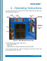
Page 37: ...rols for the System s ignition switch Pump clutch Pump out switch for Automatic Wastetank Dump System AWDS The front dash assembly also includes the temperature control dial the vacuum and pressure gauges and the hour meter Figure 4 1 TMTG 4000 Upper Dash Assembly Vacuum Gauge Pressure Gauge Ignition Switch Choke Throttle Temperature Control Dial Auto Pump Out Switch Pump In Pump Clutch Switch Hou...

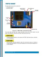
Page 38: ...To ensure proper operation of the system the TMTG 4000 must have a minimum of 10 Hg vacuum Never perform cleaning operations when the truckmount engine is running at the IDLE throttle position To do so will increase the risk of serious component or engine damage Figure 4 2 TMTG 4000 Lower Dash Assembly Blower Lube Port Solution Out Chemical Flow Meter Incoming Fresh Water Water Box Drain Chemical ...

Page 39: ...ay out and lock into place 8 Press the PUMP CLUTCH switch to engage the pump clutch for carpet cleaning or upholstery cleaning as follows a Switch to the HP Only if connected to a fresh water supply from a building b Switch to the HP On Pump In ON if connected to a non pressurerized water source such as a fresh water tank 9 Set the TEMPERATURE CONTROL dial to the desired position a Set to the WARM...

Page 40: ...METER at full flow for 30 seconds c Turn the CHEMICAL SYSTEM valve to ON The restriction can now be removed from the vacuum inlet d While spraying solution from the cleaning tool adjust the chemical flow by turning the CHEMICAL METERING CONTROL knob 13 Begin cleaning WATER EXTRACTION PROCEDURE To perform water extraction set the PUMP CONTROL switch to the Flood Extraction position This will diseng...

Page 41: ... Spray a HydraMaster recommended spray lubricant into the BLOWER LUBE PORT for about 5 to 7 seconds while the unit is running see Figure 4 2 d Allow machine to run additional 2 to 5 minutes under load to flush off lubricant e Uncap the inlet s and run the unit for another minute to allow the blower to cool down 5 If freeze guarding is necessary perform the procedure at this time See the Freeze Gua...

Page 42: ... provided in the Owner s Manual must be correctly and completely filled out HydraMaster may request to inspect the logs before a warranty claim is honored It is recommended that the log be affixed to the vehicle door near the truckmount for convenience and to serve as a maintenance reminder This section describes how to properly maintain the truckmount in the following areas Operational Maintenanc...

Page 43: ...relief valve Clean and lubricate as necessary Clean the recovery tank thoroughly with pressure washer Check the pump belt for wear and proper tension Adjust as needed Check all the hoses and wiring for wear and chafing Secure as needed Flush the water and chemical systems with solution of equal parts white vinegar and water Check all the nuts and bolts Tighten as needed One time change of the high...

Page 44: ...Check the fuel lines every 250 hours Repair or replace as needed Check valve clearance intake and exhaust 0 004 to 0 006 every 250 hours 500 Hours Change blower oil every 500 hours Change the high pressure pump oil every 500 hours Change fuel filter every 500 hours Check coupler element rubber insert for cracks or wear Replace as necessary 1 000 Hours Check plug wires Replace as necessary every 1 ...

Page 45: ...ghly with a damp cloth Wipe down the vacuum and high pressure hoses as needed Inspect and clean the vacuum slot on the cleaning wand Check the wand head for sharp edges that could tear carpet File down as needed Clean the wand to maintain original appearance Visually inspect the hoses for abrasions cuts etc Repair or replace as needed Weekly Empty the chemical container Wash out thoroughly to remo...

Page 46: ...cing engine oil be sure the oil meets or exceeds the recommended specification Changing Engine Oil and Filter The engine oil and filter must be changed every 50 hours or every 3 months whichever occurs first The oil and filter should be changed more often if the engine is operating in dusty or extremely dirty areas or during periods of high ambient temperature Engine Oil Quality To achieve proper ...

Page 47: ...en another turn Fill the engine with the correct amount of oil run the engine and check for oil leaks at the drain plug and oil filter gasket Spark Plugs Always use the recommended spark plugs for your engine Hotter or colder plugs or similar plugs that are not exact equivalents to the recommended plugs can cause permanent engine damage reduce the engines useful life and cause many other problems ...

Page 48: ...ne of the oil seals may be damaged Do not operate the pump if the crankcase oil has become contaminated Do not rotate the drive shaft without oil in the crankcase reservoir The pump should never be run dry Running the pump dry will cause premature wear on the seals packing and plungers Running the pump dry for a prolonged period of time may cause damage that cannot be repaired and voids warranty D...

Page 49: ...on and delivery check valves The valve assembly usually stays together when removing If the valve comes apart use the needle nose pliers or reverse pliers to remove the remaining parts 4 Inspect each suction and delivery check valve assembly for wear and pitting and replace if necessary The valve assembly consists of the plastic cage spring valve seat poppet and O ring One valve kit is needed for ...

Page 50: ...cking Maintenance 1 Remove the manifold as previously described It is possible that the seal and brass retainer ring assembly will stay on the piston or will remain in the manifold when removing it 2 Carefully remove the brass retainer ring seal stack Remove the low pressure seal using needle nose pliers Discard the old seal 3 Remove the outer O ring by taking a small flat head screwdriver and wor...

Page 51: ...ce if necessary Plunger Re assembly 1 Generously grease the piston guide Replace the O ring making sure it does not twist or roll 2 Slide the lower washer and ceramic bushing onto the piston guide 3 Place a small amount of LOCTITE 243 on the piston guide threads Replace the old washer and thread the nut onto the piston guide Torque to 4 5 ft lbs Servicing the Crankcase 1 While the manifold and plu...

Page 52: ...throughtheblowercanleadtoseriousproblemswiththetruckmount It is important to keep the vacuum tank free of foam The tank is protected from overflowing by a float kill switch however this switch is not activated by foam Daily At the end of each day the internal components of the blower need to be lubricated This helps to prevent rust deposits and prolongs the life of the truckmount Lubricate the blo...

Page 53: ... 000 078 058 start with an empty water box Fill a third of the water box with TM DeScaler Follow the recommendations on the TM DeScaler label for proportions Verify that the float is not laying horizontal but floats at an angle below the shutoff line Attach the recirculation fitting provided in the kit to the garden hose quick connect see Figure 5 2 and this combination to the front of the truckmo...

Page 54: ...f antifreeze follow local laws and regulations Do not discard into storm sewers septic systems or onto the ground Antifreeze is harmful or fatal if swallowed Do not store in open or unlabeled containers Keep out of reach of children and animals When draining solution from the machine wear protective eye wear and ensure the solution temperature is cold Failure to follow this caution can result in p...

Page 55: ... line 4 Start the truckmount and allow it to run for 2 3 minutes This will distribute antifreeze solution throughout the truckmount 5 Remove the chemical feed line from the chemical jug Turn the CHEMICAL SYSTEM valve to PRIME This will vacuum the chemical remaining in the lines to the recovery tank 6 Remove the quick connect from the truckmount 7 Spray the antifreeze and water mix out of the truck...

Page 56: ...truckmount 2 Attach the incoming water source to the front of the truckmount 3 Start the truckmount 4 Spray the solution through the hoses and wands into a sealable container until all signs of antifreeze are gone Freeze Protection of the Pump In System 1 Drain the fresh water tank 2 Remove the garden hose adapter from the pump in pump hose and position the hose so it is pointing outside the van 3...

Page 57: ... a temperature sensor inside the high pressure manifold When the system achieves the maximum operating temperature the high pressure solenoid opens and flows water into the recovery tank This will reduce the internal temperature of the machine 5 Water that is recirculated through the pressure regulator back to the water box travels past a thermal valve This thermal valve monitors the water box tem...

Page 58: ...6 3 Water and Chemical System Figure 6 1 Flow Diagram View 1 of 3 000 179 038 Rev A ...

Page 59: ...Water and Chemical System 6 4 Figure 6 2 Flow Diagram View 2 of 3 000 179 038 Rev A ...

Page 60: ...6 5 Water and Chemical System Figure 6 3 Flow Diagram View 3 of 3 000 179 038 Rev A AWDS DRAIN FLOW AWDS FLOAT SWITCH AWDS PUMP AWDS OUT ...

Page 61: ... Electrical Schematic Wiring Diagram ELECTRICAL SYSTEM INFORMATION The TMTG 4000 electrical system operates on 12 V DC which is provided by the battery Battery levels are maintained by a 20 Amp alternator mounted on the engine When a new battery is installed check that it is properly charged before installation or damage to the charging system may occur ...

Page 62: ... FRESH WATER PUMP IN OPTION PUMP IN PUMP TEMP SENDER TT 1 TB1 2 TB2 5 TB2 2 PMP 1 AWDS PUMP AWDS PUMP OPTION TB2 6 TB2 6 GND 30 85 87a 86 87 FS 3 N O AWDS FLOAT AWDS RELAY CR 2 12V BATTERY PS 1 1 2 3 4 5 6 IGNITION SWITCH SW 1 MAIN 30A FUSE FU 1 GREEN BLACK WHITE RECOVERY TANK FLOAT SWITCH 86 30 85 87 87A N O N C RELAY SCHEMATIC SHOWN IN OFF POSITION VOLTAGE REGULATOR VR 1 STATOR STARTER ST BATT C...

Page 63: ...TCH PUMP IN PUMP SWITCH SW 2 31 GRN TO PUMP IN PUMP PMP 1 46 GRY 6 5 4 3 2 1 TO INLINE FUSE FU 1 35 ORG TO GROUND AT REGULATOR 16 BRN 38 BLU WHT TO ENGINE KILL LUG 02 BLK TO STARTER SOLENOID SOL 1 10 YEL IGNITION SWITCH SW 1 36 WHT TO TB1 4 13 PUR WHT TO LOW WATER ENGINE STOP FS1 18 GRN WHT TO CARB SOLENOID V 1 16 GA 01 RED 24 PNK 31 GRN 2 P1 1 1 4 5 6 TO PUMP CLUTCH RELAY CR 1 44 RED BLK 45 BLK A...

Page 64: ...GA 13 PUR WHT 15 WHT 14 GA 07 ORG 14 GA 06 ORG 14 GA B 1 40 WHT 39 WHT 14 GA 08 RED 6 GA ENGINE GROUND 08 RED 6 GA 11 BLK 6 GA 05 RED 6 GA AWDS OPTIONAL BLK D1 1 2 3 4 5 6 TB1 WHT BLK AWDS FLOAT FS 3 WHT BLK VACUUM TANK FLOAT SWITCH FS 2 AWDS RELAY CR 2 42 BLK BLK BLK BLK 30 BRN 14 GA BLK WHT 02 BLK 12 RED 16 GA B S ENGINE STARTER STARTER SOLENOID VOLT REG MTR 1 SOL 1 BATT VR 1 ST PUMP CLUTCH RELA...

Page 65: ...ystems Troubleshooting 8 Systems Troubleshooting This section describes the standard troubleshooting procedures in the following areas Heating System Chemical System Engine High Pressure System Vacuum System ...

Page 66: ...o a qualified service technician to test the temperature controller and sensor 2 0 Unable to achieve normal cleaning solution temperature Possible Cause Solution 2 1 Temperature control knob is turned down Inspect the knob Adjust if necessary 2 2 The dump solenoid is faulty Inspect the solenoid and test for functionality If the solenoid is operable refer to a qualified service technician to test t...

Page 67: ...s Replace as necessary 2 0 Chemical flow is unstable or low Possible Cause Solution 2 1 Air is in the lines Check that all fittings and connections are tight and in good condition Repair or replace as necessary 2 2 The filter screen in the chemical jug is partially obstructed Inspect and clean 2 3 The chemical selector valve is faulty Inspect the valve for leaks between ports Replace as necessary ...

Page 68: ...e electrical system for worn or shorted wires Repair or replace as necessary 1 4 The vacuum blower has seized Attempt to turn the coupler by hand If it will not turn refer to the Vacuum System Troubleshooting Section 1 5 The ignition switch is faulty Test to see if there is power both to and from the switch Refer to the Electrical Section 1 6 The starter solenoid is faulty Test to see if there is ...

Page 69: ... check for spark refer to engine manual Possible Cause Solution 3 1 Fuel tank is empty Check the fuel level and fill tank if necessary 3 2 Fuel filters are clogged Remove and replace fuel filters 3 3 Fuel is not reaching the carburetor Test for power to the fuel pump Refer to Electrical Section If power is present inspect the fuel pump Replace if necessary Inspect the fuel lines between the source...

Page 70: ... are faulty Remove and inspect the plugs Clean or replace as necessary 5 2 The spark plug wire s are faulty Inspect the wires and connectors for damage or loose connections Repair or replace as necessary 5 3 Inadequate fuel supply to the carburetor Check if the fuel pump is mounted in a vertical position near the fuel source Correct if necessary Check for blockage in the filter Repair or replace a...

Page 71: ... level Check the level and fill as necessary Running the engine with a low oil level can cause severe damage to the engine If this situation occurs the engine should be inspected by a qualified service technician 7 3 The engine rpm is too high Check the engine rpm Adjust as necessary to run at 3 200 rpm under no vacuum load 7 4 Excessive back pressure on the engine exhaust Inspect for blockage in ...

Page 72: ...econdary orifices have been installed incorrectly Inspect and reverse if necessary Refer to the Machine Assemblies Parts List Section 1 6 The primary orifice is worn Measure the orifice size and replace as necessary Correct size is 0 021 2 0 No pressure reading on gauge Possible Cause Solution 2 1 The pump belt is broken Inspect and replace if necessary 2 2 The gauge is faulty Replace the gauge 3 ...

Page 73: ...estriction in the water supply system Inspect the supply system from the source through the incoming quick connect 5 2 The float valve in the water box is faulty Disassemble and inspect the valve Repair or replace as necessary 6 0 The water box overflows Possible Cause Solution 6 1 The float valve in the water box is faulty Disassemble and inspect the valve Repair or replace as necessary 6 2 The f...

Page 74: ...slowly Check the rpm of the engine Adjust as necessary to 3 200 rpm under no vacuum load 2 3 The vacuum gauge is defective Test the gauge and replace if necessary 3 0 The vacuum gauge reads too high with no hoses attached Possible Cause Solution 3 1 The filter in recovery tank is clogged Remove and clean or replace as necessary 3 2 The hose from recovery tank to the vacuum blower is collapsed inte...

Page 75: ...up the blower in this manner refer to a qualified service technician 5 2 There is internal damage to the blower Refer to a qualified service technician 6 0 Water in truckmount exhaust Possible Cause Solution 6 1 The recovery tank has been filled with foam or overfilled with water Inspect the recovery tank If full drain the tank Inspect the high level shutoff switch for proper operation Clean or re...

Page 76: ...s the Enter key Truckmount to Go 4000 Parts List 9 9 Truckmount to Go 4000 Console Parts List 9 14 Frame Assembly Parts List 9 16 Blower Assembly Parts List 9 19 Pump Assembly Parts List 9 20 Dash Assembly Parts List 9 24 Differential Check Valve Assembly Parts List 9 25 By Pass Valve Assembly Parts List 9 26 Orifice Assembly Parts List 9 27 Engine Assembly Parts List 9 29 Blower Heat Exchanger As...

Page 77: ...e and lubricant specifications that are used in the construction of HydraMaster equipment Refer to Figure 9 1 to identify those substances such as A1 A2 and so forth Equivalent products are acceptable if they meet or exceed current specifications and are approved by HydraMaster Figure 9 1 Adhesive Sealant Material Reference ...

Page 78: ...750 013 756 10 Rev A 36 000 081 508 LABEL TIE DOWN LOCATION 2 000 081 509 LABEL DO NOT LIFT 2 1 1 1 1 74 73 72 71 70 69 68 67 66 65 64 63 62 61 60 59 58 57 56 55 54 53 52 51 50 49 48 47 46 45 44 43 42 41 40 39 38 37 36 35 34 33 32 31 30 29 28 27 26 25 24 23 22 21 20 8 7 6 5 4 3 ...

Page 79: ...9 4 Assemblies and Parts Lists Figure 9 3 Truckmount to Go 4000 View 2 of 6 750 013 756 10 Rev A 36 57 000 46 750 61 040 44 000 NOTES 1 ITEM NOT SHOWN 2 PART OF LABEL SET 0 3 4 5 6 7 8 ...

Page 80: ... 7 GA 65 1 SWITCH F 64 1 SLEEVE S 63 6 SCREW 5 62 4 SCREW 5 61 4 SCREW 5 60 8 SCREW 3 59 4 SCREW 3 58 6 SCREW 3 57 2 SCREW 3 56 6 SCREW 3 55 17 SCREW 3 54 2 SCREW 1 53 1 SCREW 1 52 2 SCREW 1 51 2 SCREW 1 50 2 RIVET 1 8 49 1 RAIL UPPE 48 1 PUMP FUE 47 1 PROTECTO 46 1 PROTECTO 45 1 PLATE MA 44 1 PLATE FUE 43 1 PLATE FUE 42 6 NUT 5 16 41 2 NUT 3 8 1 40 4 NUT 1 4 2 39 2 NUT 1 4 2 38 2 MOUNT HO 37 1 LA...

Page 81: ...9 6 Assemblies and Parts Lists Figure 9 5 Truckmount to Go 4000 View 4 of 6 750 013 756 10 Rev A DETAIL A SCALE 1 4 59 4X 73 4X 5 74 2X 63 2X 6 51 2X 69 2X 8 47 4 13 24 30 10 21 46 13 64 D 3 2 1 E F ...

Page 82: ...ER VARIOUS 000 108 220 46 1 PROTECTOR BATTERY TMTG GRISWOLD NATURAL RUBBER 3120 R012 000 108 233 45 1 PLATE MACHINE SERIAL I D 1100 H14 000 105 012 44 1 PLATE FUEL TANK RISER PAN 5052 H32 000 105 804 43 1 PLATE FUEL TANK RISER 5052 H32 000 105 803 42 6 NUT 5 16 18UNC HEX NYLOCK 18 8 S STEEL 000 094 038 41 2 NUT 3 8 16UNC HEX Z P ZINC PLATED 000 094 014 40 4 NUT 1 4 20UNC HEX Z P STEEL 000 094 008 ...

Page 83: ...iew 6 of 6 750 013 756 10 Rev A DETAIL A SCALE 1 4 66 7 2X 74 63 4X 23 12 2X 30 10 43 34 DETAIL B SCALE 1 4 14 17 11 71 53 11 26 11 48 72 2X 40 2X 25 11 25 20 74 6X 61 4X 62 4X 74 6X 42 6X D C B PROPRIETARY INFORMATION 11015 47th Avenue West Mukilteo Washington 98275 ...

Page 84: ...068 065 HOSE 2 X 50 VACUUM BLUE 2 30 000 068 1059 HOSE 3 4 I D RUBBER X 50 LG AWDS OUTLET 1 31 000 068 035 HOSE 5 8 x 50 GARDEN 1 32 000 052 098 INSERT 25 1 33 000 052 096 INSERT F23 1 8 FPT x 3 16 BARB 1 34 000 052 758 INSERT 1 NPT x 1 BARB 1 35 000 159 262 JUG 2 5 GALLON RECTANGLE HDPE 1 36 000 079 220 KIT AWDS UNIVERSAL 1 37 000 081 507 LABEL SET TMTG LIFTING TIE DOWN 1 38 000 092 063 MOUNT HOO...

Page 85: ... 012 SCREW 5 16 18UNC x 3 4 LG HEX HEAD 6 64 000 152 009 SLEEVE SOLENOID INSULATOR 1 65 000 157 091 SWITCH FLOAT LEVER 1 66 000 159 264 TANK 7 GALLON FUEL w GAUGE 1 67 000 166 077 TRAY SOAP JUG 2 5 1 68 000 163 034 WAND 1 5 ALUMINUM 1 69 000 174 001 WASHER 10 FLAT 2 70 000 174 055 WASHER 0 390 I D x 0 625 O D x 0 06 THK FLAT 8 71 000 174 002 WASHER 1 4 FLAT 1 72 000 174 003 WASHER 1 4 FLAT S S 6 7...

Page 86: ...N x 24 LG HX TO ORIFICE ASSY S STEEL 000 068 888 22 1 HOSE 3 16 I D TEFLON x 23 LG CHEM PUMP TO PRIME CHEM METERING TO SOL OUT VARIOUS 000 068 517 21 1 HOSE 3 16 I D TEFLON x 18 25 LG PUMP TO GAUGE S STEEL 000 068 518 20 1 HOSE 1 2 I D RUBBER x 69 LG FRESH WATER IN TO WB RUBBER 000 068 969 19 1 HOSE 1 2 I D RUBBER x 56 LG PUMP TO WB RUBBER 000 068 968 18 1 HOSE 1 2 I D RUBBER x 20 LG WB DRAIN RUBB...

Page 87: ...v A 3 9 4 5 8 20 13 19 24 13 25 24 19 23 28 12 21 32 26 11 31 30 18 13 13 13 22 PART OF FRAME HIDDEN FOR CLARITY 21 33 13 22 D C B 4 3 2 1 E F PROPRIETARY INFORMATION 11015 47th Avenue West Mukilteo Washington 98275 1 7 10 12 12 28 22 22 18 13 12 35 36 36 27 29 29 25 6 33 32 26 11 B C D 8 7 6 5 4 E F ...

Page 88: ... 30 940 31 937 28 000 D C B A A B C D 1 3 4 5 6 7 8 8 7 6 5 4 3 2 1 E F E F SCALE 1 4 SHEET 3 OF 3 PROPRIETARY INFORMATION 11015 47th Avenue West Mukilteo Washington 98275 D SIZE PART NUMBER CODE 610 050 756 REV ASSEMBLY CONSOLE TMTG 4000 A L R K L R K L O L DRAWN CHECKED APPVD 06 03 2019 06 05 2019 06 05 2019 455 89 WEIGHT ...

Page 89: ...000 068 518 HOSE 3 16 I D TEFLON x 18 25 PMP TO GAUGE 1 22 000 068 517 HOSE 3 16 I D TEFLON x 23 CHEM PUMP TO PRIME CHEM METERING TO SOL OUT 1 23 000 068 888 HOSE 3 16 I D TEFLON x 24 HX TO ORI ASSY 1 24 000 068 203 HOSE 3 16 I D TEFLON x 34 OR ASSY TO WB 1 25 000 068 627 HOSE 3 16 I D TEFLON x 44 OR ASSY TO R TANK 1 26 000 068 970 HOSE 3 4 I D RUBBER x 50 PUMP TO WB 1 27 000 068 980 HOSE 3 8 I D ...

Page 90: ...D REMOVED NOTATED 081 408 081 327 UPDATED NOTE 1 055 195 WAS REVISED ECR 2464 11 15 2013 S M W C I R ECRB E MOVED 105 012 140 001 TO CONSOLE ECR 2520 05 15 2014 L O L C I R ECRB 17 1 WASHER 5 16 LOCK S STEEL 000 174 018 D C E F P N 000 081 327 is part of label set P N 000 081 728 Only label sets can be sold individual labels not available for sale ...

Page 91: ...18UNC x 3 4 LG HEX HEAD 2 13 000 143 583 SCREW 10 24UNC x 0 50 LG HEX FLANGE Z P 1 14 000 157 022 SWITCH RELAY 12V 2 15 000 131 131 TRIMLOK 3 8 x 1 8 RUBBER BULK 1 16 000 174 004 WASHER 5 16 FLAT USS 1 17 000 174 018 WASHER 5 16 LOCK 1 Item Part Number Description Qty 1 610 021 009 ASSEMBLY IDLER PULLEY 1 2 610 021 724 ASSEMBLY SILENCER 1 3 000 015 177 BRACKET DUAL HEAT XR MOUNTING LEFT CTD 1 4 00...

Page 92: ...ve sealant information 0 75 0 25 0 75 0 25 0 188 0 125 2 9 14 4X 17 4X 6 2X 10 8 4 2X 17 4X 11 4X 8 1 12 6X 7 2X 5 2X 18 4X 13 6X 17 4X 3 000 027 112 CAP OIL SIGHT GLASS 000 027 112 CAP OIL SIGHT GLASS MOVE BOTH VENTS TO THIS SIDE 17 4X 15 4X A1 A3 A3 A3 16 2X TORQUE TO 40 FT LBS A1 B1 TORQUE TO 40 FT LBS B C D E F ...

Page 93: ...O 30 FT LBS 6 2X 10 8 4 2X 17 4X 11 4X 8 1 12 6X 000 027 112 CAP OIL SIGHT GLASS 000 027 112 CAP OIL SIGHT GLASS A1 COUPLER B1 2X TORQUE TO 30 FT LBS B1 3X B1 2X TORQUE TO 30 FT LBS REUSE MAGNETIC PLUG REMOVED TO INSTALL HOSE A4 LTR REVISION DESCRIPTION CODE DATE BY CHKD APPVD A RELEASE DRAWING NEW 05 23 2019 L O L L R K L R K D C 3 2 1 E F Add Shims as necessary to all four mounting bolts to alig...

Page 94: ...94 HOSE ASSEMBLY 3 8 x 17 LG DRAIN 2 9 000 052 293 INSERT 23 1 8 NPT x 3 16 BARB 2 10 000 077 011 KEY 3 16 X 1 1 2 LONG 1 11 000 094 015 NUT 3 8 16UNC HEX 2 WAY LOCKING 4 12 000 143 141 SCREW 1 4 20UNC x 0 50 LG WHIZ LOCK 6 13 000 143 018 SCREW 3 8 16UNC X 1 00 LG HEX HEAD G8 6 14 000 143 094 1 SCREW 3 8 16UNC x 0 75 LG SOCKET HEAD 4 15 000 143 200 SCREW 3 8 16UNC x 1 50 LG HEX HEAD G8 4 16 000 17...

Page 95: ...E DIMENSIONS ARE IN BREAK ALL SHARP EDGES M TOLERANCES X 1 16 2X 18 2X REVISIONS LTR DESCRIPTION CODE DATE BY CHKD APPVD A NEW DRAWING NEW 04 02 2015 C I R L O L ECRB B REPLACED 1 QTY 610 009 729 WITH 610 009 747 ECR 2742 11 16 2016 PE L O L ECRB 18 6 WASHER 5 16 FLAT USS STEEL 000 174 004 17 4 SCREW M6 1 X 14MM LG HEX HEAD STEEL 000 143 221 16 2 SCREW 5 16 18UNC x 3 4 LG S STEEL 000 143 012 15 2 ...

Page 96: ... INSERT 26 1 8 NPT x 3 8 BARB 1 9 000 052 129 INSERT 812 1 2 NPT X 3 4 BARB 1 Item Part Number Description Qty Item Part Number Description Qty 10 000 094 038 NUT 5 16 18UNC HEX NYLOCK 2 11 000 097 057 O RING ADAPTER CHEMICAL PUMP 1 12 000 105 148 PLATE CLUTCH MOUNT COMET PUMP 1 13 000 111 184 PUMP GP CHEMICAL 1 14 000 111 042 PUMP HYDRAPUMP II 1 15 000 143 375 SCREW 5 16 18UNC x 1 75 LG HH GRD 8 ...

Page 97: ...GNITION B S COMES WITH 000 047 028 000 081 328 LABEL ANSI WARNING LARGE 000 081 416 LABEL DASH RESTORATION RIGHT 000 081 331 LABEL TEMPERATURE 000 081 410 LABEL THERMOSTAT 000 081 405 LABEL DASH CONTROL LEFT KNOB CHEMICAL SELECTOR COMES WITH 39 35 5 30 18 24 2X 21 13 50 13 8 41 39 19 11 11 31 2X 44 2X 43 2X 24 52 42 7 45 20 1 1 1 1 1 3 B C D 8 7 6 5 4 E F See Figure 9 1 for adhesive sealant inform...

Page 98: ...X HEAD S STEEL 000 1 31 2 SCREW 10 24UNC x 0 375 LG HEX HEAD S STEEL 000 1 30 1 REGULATOR HI PSI SNUBBER BRASS 000 1 29 1 QUICK CONNECT 660 3 8 BRASS W EPDM O RING BRASS 000 0 28 1 QUICK CONNECT 440 FEMALE w EPDM O RING BRASS 000 0 27 1 PANEL GRILL BLANK BOXXER COATED 5052 H32 000 1 26 1 PANEL DASH STEEL COATED STEEL 000 1 25 1 NUT 7 16 24UNF 2 WAY METERING VALVE STEEL 000 0 24 4 NUT 5MM HEX NYLOC...

Page 99: ...25 000 094 098 NUT 7 16 24UNF 2 WAY METERING VALVE 1 26 000 100 310 PANEL DASH STEEL COATED 1 27 000 100 378 PANEL GRILL BLANK BOXXER COATED 1 28 000 052 051 QUICK CONNECT 440 FEMALE w EPDM O RING 1 29 000 052 052 QUICK CONNECT 660 3 8 BRASS W EPDM O RING 1 30 000 135 052 REGULATOR HI PSI SNUBBER 1 31 000 143 166 SCREW 10 24UNC x 0 375 LG HEX HEAD 2 32 000 143 126 SCREW 10 24UNC x 0 50 LG HEX HEAD...

Page 100: ...a Stainless Steel 1 2 000 107 258 Body Differential Check Valve 1 3 000 106 180 Cap Differential Check Valve 1 4 000 097 056 O Ring Check Valve Plug AN Size 118 Vit 1 5 000 097 054 O Ring Chem Pump Valve Viton Parker 2 114 1 6 000 148 012 Seat Differential Check Valve 1 7 000 155 106 Spring Differential Check Valve 1 Item Part Number Description Qty Item Part Number Description Qty ...

Page 101: ...BRASS 000 052 086 LTR REVISION DESCRIPTION CODE DATE BY CHKD APPVD A DRAWING RELEASED NEW 10 8 2015 L O L C I R C I R B ITEM 3 WAS 052 528 LRIP 02 02 2016 C I R L O L C I R D C B 4 3 2 1 E F A ASSEMBLY BY PASS VALVE CTS 400 FLEX UNLESS OTHERWISE NOTED DIMENSIONS ARE IN INCHES BREAK ALL SHARP EDGES 0 005 015 11015 47th Avenue West Mukilteo Washington 98275 PROPRIETARY INFORMATION 125 MACHINE FINISH...

Page 102: ...B C D 8 7 6 5 4 3 2 1 A PROPRIETARY INF 11015 47th Aven Mukilteo Washing TOLERANCES X 1 XX 03 XXX 010 ANGULAR 2 BREAK ALL SHARP EDGES 0 005 015 UNLESS OTHERWISE NOTED DIMENSIONS ARE IN INCHES ASSEMBLY ORIFICE MACHINE FINISH 125 Orifice Assembly Parts List 1 000 052 084 ELBOW 1 8 NPT STREET 1 2 000 049 052 FILTER CARTRIDGE 1 4 BRASS 2 3 000 052 153 HOUSING STABILIZER NOZZLE 2 4 000 052 530 NIPPLE 1...

Page 103: ...9 28 Assemblies and Parts Lists Figure 9 21 Engine Assembly View 1 of 2 610 004 728 Rev E See Figure 9 1 for adhesive sealant information ...

Page 104: ...0 Lg 1 13 000 077 010 Key 1 4 X 1 1 2 Lg Class 2 Fit 2 14 000 094 012 Nut 5 16 18UNC Hex 1 15 000 094 081 Nut 5 16 18UNC Hex 2 Way Locking 4 16 000 094 125 Nut 6mm Hex Nylock Flange S S 4 17 000 105 562 Plate Engine Duct Coated 1 18 000 109 040 Pulley AK47 H 1 19 000 140 001 Rivet AB4 3A Aluminum Pop 1 8 X 1 4 Lg 12 20 000 143 659 Screw 5 16 18UNC X 3 5 Lg Grade 8 2 21 000 143 660 Screw 5 16 18UNC...

Page 105: ...hanger Assembly 610 005 754 Rev A 3 16 4X 13 2 8 14 17 15 9 18 6 1 11 7 7 12 10 4 2X 5 2X 4 2X 5 2X 10 16 16X 16 16X SENSOR COMES WITH 000 149 025 18 1 TEE 17 1 SEN 16 36 SCR 15 1 NIPP 14 1 NIPP 13 1 NIPP LTR A RELE 8 7 6 5 4 3 SeeFigure9 1forsealantinformation ...

Page 106: ...038 001 CORE BLOWER HEAT EXCHANGER 1 9 000 052 113 CROSS 3 8 FPT 1 Item Part Number Description Qty Item Part Number Description Qty 10 000 057 255 GASKET SALSA HX CDS ZR 2017 2 11 000 068 986 HOSE 2 5 HEAT FLEX NS x 15 LG 1 12 000 052 528 NIPPLE 3 8 M JIC x 3 8 NPT 1 13 000 052 128 NIPPLE 3 8 MPT x 3 8 SAE FLARE 1 14 000 052 074 NIPPLE 3 8 NPT HEX 1 15 000 052 662 NIPPLE 3 8 NPT x 1 4 M SAE 1 16 ...

Page 107: ...154 049 6 1 SCREW 1 4 20UNC x 4 00 LG S S FULL THREAD S STEEL 000 143 376 5 1 SCREW 1 2 13 X 2 1 2 HHC ZINC S STEEL 000 143 716 4 1 PULLEY 3 A SECT BALL BEARING ASSEMBLY STEEL 000 109 093 3 1 NUT 1 4 20UNC NYLOCK S STEEL 000 094 009 2 1 NUT 1 2 13UNC SQUARE Z P STEEL 000 094 119 1 1 BRACKET IDLER TENSION COATED VARIOUS 000 015 942 D C B A B C D 1 2 3 4 5 6 7 8 E F E A ASSEMBLY IDLER PULLEY C REV 6...

Page 108: ... 780 LRIP 2 12 2008 L O L B R T B R T B UPDATED TITLE BLOCK MIT 7 5 2011 DMR LRK LRK 3 1 SILENCER Ø2 5 OD INLET OUTLET COATED STEEL 000 093 108 2 2 HOSE Ø2 5 ID x 2 5 LG SILICONE 000 068 104 1 4 CLAMP SIZE 44 HOSE S STEEL 000 033 012 ITEM NO QTY DESCRIPTION MATERIAL PART NO D C B A B C D 8 7 6 5 4 3 2 1 E F E F A ASSEMBLY SILENCER UNLESS OTHERWISE NOTED DIMENSIONS ARE IN INCHES BREAK ALL SHARP EDG...

Page 109: ...X 1 1 7 5 10 A3 A3 A3 A3 A3 H H H H H H H G A3 A3 A2 NOT THE ACTUAL LENGTH OF THE HOSE USE A 13 16 DRILL BIT TO ROUTE THE OVERFLOW HOSE TO THROUGH THE VAN S FLOOR NOTES 1 SEE ENG 45975 OR ADHESIVE MATERIAL PRODUCTION LINE REFERNCE CARD FOR SEALANT INFORMATION SEE DRAWING FOR ASSEMBLY INSTRUCTIONS 2 2 A B C D 3 4 5 6 7 8 E See Figure 9 1 for adhesive and sealant information ...

Page 110: ...PLE 3 8 NPT x 1 4 M SAE 1 15 000 094 097 NUT 1 14UNS BRASS 4 16 000 097 041 O RING 1 2 BULK HEAD 2 17 000 143 017 1 SCREW 3 8 16UNC x 0 75 LG HEX HEAD 3 18 000 143 739 SCREW 8 15 X 3 4 LG PAN HEAD SHT MTL SS 6 19 000 157 0801 SWITCH w PROTECTOR POLYPROPELENE 1 20 000 159 190 TANK POLY WATER BOX 4 GALLON MODIFIED 1 21 000 052 447 TEE 3 8 NPT MALE BRANCH 1 22 000 052 023 TEE 3 8 NPT MALE STREET 1 23...

Page 111: ...TERIAL PART NO 16 10 WASHER 5 16 FLAT 18 8 S STEEL 000 174 049 15 4 WASHER 1 4 LOCK S S S STEEL 000 174 019 14 4 WASHER 1 4 FLAT S S S STEEL 000 174 003 13 1 TUBE LOWER EXHAUST WELDMENT S STEEL 000 125 259 12 1 TUBE EXHAUST 8 75 LG w FLARE AISI 304 304L 000 125 954 11 4 SCREW 5 16 18UNC x 1 75 LG HEX HEAD S STEEL 000 143 124 10 4 SCREW 1 4 20UNC x 0 75 LG HEX HEAD S STEEL 000 143 001 9 6 NUT 5 16 ...

Page 112: ...ASSY USED ON TMTG 4000 750 013 756 10 L R K L R K L O L DRAWN CHECKED APPVD 0 0 0 TOLERANCES X 1 XX 03 XXX 010 ANGULAR 2 Figure 9 28 70 Gallon Universal Recovery Tank Assembly 610 003 756 Rev A 14 9 22 2X 28 4X 2 12 43 2X 33 2X 42 2X 41 2X 5 11 13 3 41 4X 10 41 4X 23 4X 27 A2 DETAIL VIEW A D 8 7 6 5 4 E F 25 17 7 37 19 38 8 13 1 41 4X 32 4X 41 4X 23 4X 43 2 WASHER 3 8 FLAT RUBBER BACKED S STEEL 00...

Page 113: ...000 094 063 NUT 6 32UNC HEX NYLOCK 4 22 000 094 059 NUT 8 32UNC HEX NYLOCK 2 23 000 094 009 NUT 1 4 20UNC NYLOCK 8 24 000 106 049 PLUG 1 NPT BLACK NYLON 1 25 000 106 019 PLUG 1 1 2 NPT 1 26 000 106 046 PLUG 1 1 4 NPT 1 27 000 108 179 PROTECTOR VACUUM RELIEF COATED 1 28 000 140 023 RIVET AB8 6A ALUMINUM POP 4 29 000 143 132 SCREW 10 24UNC x 0 75 LG HEX HEAD 1 30 000 143 539 SCREW 6 32UNC x 0 50 LG ...

Page 114: ...000 094 063 7 2 GASKET SIDE RECOVERY TANK RUBBER 000 057 204 6 2 GASKET MIDDLE REC TANK COVER RUBBER 000 057 203 5 2 GASKET END REC TANK COVER RUBBER 000 057 202 4 1 GASKET 1 1 2 BULKHEAD FITTING VARIOUS 000 057 015 3 1 ELBOW 2 BARB x 2 FPT ABS 000 052 222 2 1 COVER 70 URT 1 PORT COATED E10 5052 H32 000 041 443 1 1 ADAPTER 2 NPT x 2 F SLIP ABS 000 052 219 D C B A 1 2 3 3 2 1 E F MACHINE FINISH 125...

Page 115: ...ED E10 1 3 000 052 222 ELBOW 2 BARB x 2 FPT 1 4 000 057 015 GASKET 1 1 2 BULKHEAD FITTING 1 5 000 057 202 GASKET END REC TANK COVER 2 6 000 057 203 GASKET MIDDLE REC TANK COVER 2 7 000 057 204 GASKET SIDE RECOVERY TANK 2 8 000 094 063 NUT 6 32UNC HEX NYLOCK 4 9 000 143 539 SCREW 6 32UNC x 0 50 LG BUTTON HEAD 4 Item Part Number Description Qty Item Part Number Description Qty ...

Page 116: ... 12 2018 L O L C I R C I R APPLICATION 000 163 633 CRADLE TANK NEXT ASSY USED ON D C B A A B C D 1 2 3 4 5 6 7 8 8 7 6 5 4 3 2 1 E F E F MACHINE FINISH 125 SCALE 1 4 SHEET 1 OF 1 PROPRIETARY INFORMATION 11015 47th Avenue West Mukilteo Washington 98275 D SIZE BREAK ALL SHARP EDGES 0 005 015 UNLESS OTHERWISE NOTED DIMENSIONS ARE IN INCHES PART NUMBER WEIGHT APPLICATION NEXT ASSY USED ON 000 163 603G...

Page 117: ...032 Cap Spun Vacuum Relief Valve 1 3 000 094 101 Nut 3 8 16 UNC Hex Jam 1 4 000 094 077 Nut 3 8 16UNC X 1 00 O D Knurled 2 5 000 105 332 Plate Vacuum Relief Valve Mounting Coated 1 6 000 143 198 Screw 3 8 16UNC X 4 Lg Hex Head Full Thread 1 7 000 155 026 Spring Vacuum Relief Valve 1 8 000 125 111 Tube Vacuum Relief Spring Guide 1 Item Part Number Description Qty Item Part Number Description Qty ...

Page 118: ...D x 1 073 I D x 0 075 THK 1 13 000 174 032 WASHER 3 8 FLAT 3 Item Part Number Description Qty Item Part Number Description Qty 12 7 3 2 6 9 5 5 1 13 3X 8 3X ITEM NO QTY DESCRIPTION MATERIAL PART NO 13 3 WASHER 3 8 FLAT AISI 304 000 174 032 12 1 WASHER 1 5 O D x 1 073 I D x 0 075 THK S STEEL 000 174 063 11 1 WASHER 1 FLAT S STEEL 000 174 050 10 1 VALVE 3 4 FPT SWING CHECK BRASS 000 169 009 9 1 VALV...

Page 119: ...arts to you Any questions you have regarding the warranty program should be directed to the Customer Service Department at 800 426 1301 7 a m to 5 p m Monday through Friday PT We shall always endeavor to be fair in our evaluation of your warranty claim and shall provide you with a complete analysis of our findings HydraMaster warranty covers only defective materials and or workmanship for the peri...

Page 120: ...tomatic shut off system Allowing foam to pass through blower HIGH PRESSURE WATER PUMP Failure to maintain proper oil level as recommended in pump manual Failure to change oil in pump at recommended intervals Failure to protect pump against freezing Failure to maintain pump protection shut off system Failure to use water softener in hard water areas Use of improper chemicals RECOVERY TANK Failure t...

Page 121: ...ressure 1 000 psi Failure to protect against freezing HARD WATER DEPOSITS Failure to use or maintain a water softening system or a properly installed magnetic type descaler whichever might be necessary with machines operating in designated Hard Water Areas 3 0 grains or more per gallon WARRANTY PROCEDURE Warranty coverage is available to you through your local distributor If you have moved to a ne...

Page 122: ...UDING BUT NOT LIMITED TO INDIRECT SPECIAL OR CONSEQUENTIAL DAMAGES ARISING OUT OF OR IN CONNECTION WITH THE FURNISHING PERFORMANCE USE OF OR INABILITY TO USE THE MACHINE ANY EXTENSIONS OF OR MODIFICATIONS MADE TO THIS WARRANTY BY A DEALER DISTRIBUTOR OF HYDRAMASTER ARE THE SOLE RESPONSIBILITY OF THE DEALER DISTRIBUTOR HydraMaster will pay all freight and transportation charges within the United St...

Page 123: ...ions will help maintain your machine s water pump and water heating systems at peak efficiency and also help ensure fewer breakdowns HydraMaster s full line of machine accessories and chemicals can enhance cleaning performance while reducing your labor costs and include Upholstery Tools Wands Vacuum Hoses Tanks Van Accessories Hose Reels Carpet Care Detergents Rinse Agents Pre Sprays Hard Floor Ca...

Page 124: ......

Reviews: