Hydac HNS 526 User Manual Download Page 1


Bedienungsanleitung 

(Originalanleitung)


User manual


(Translation of original 

instructions) 

Notice d'utilisation 

(traduction de l'original) 
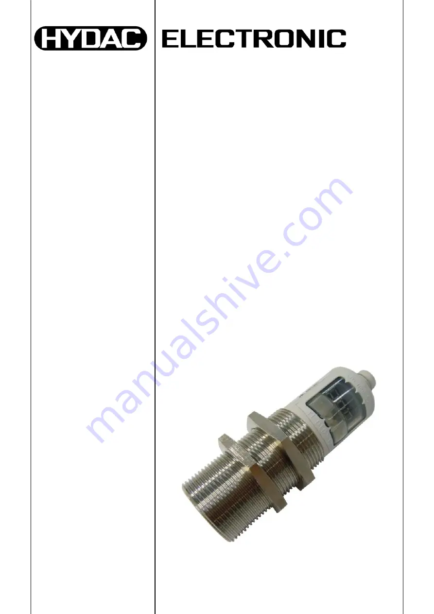


HYDAC 
Niveauschalter  

HYDAC Level 
Switch  
HYDAC Capteur de 
niveau 


HNS 526 


M

a

t –Nr.

 669869 /

 S

tand:

 06.

10.

20

14 D/

E

/F


Summary of Contents for HNS 526

Page 1: ...Originalanleitung User manual Translation of original instructions Notice d utilisation traduction de l original HYDAC Niveauschalter HYDAC Level Switch HYDAC Capteur de niveau HNS 526 Mat Nr 669869 Stand 06 10 2014 D E F ...

Page 2: ...ltpunkt SP 12 7 1 2 Einstellung auf Fensterfunktion Fno Fnc 13 7 2 Einstellbereiche der Schaltpunkte bzw Rückschaltpunkte 14 8 Inbetriebnahme 15 9 Menüführung 16 10 Anschlussbelegung 24 11 Technische Daten 25 11 1 Erfassungsbereiche bei unterschiedlichen Objekten 26 12 Bestellangaben 29 13 Zubehör für den elektrischen Anschluss 29 14 Geräteabmessungen 30 14 1 Betriebstastweite 280 mm 30 14 2 Betri...

Page 3: ... sein Bitte beachten Sie dass die in dieser Dokumentation gemachten Angaben der Gerätetechnik zu dem Zeitpunkt der Literaturerstellung entsprechen Abweichungen bei technischen Angaben Abbildungen und Maßen sind deshalb möglich Entdecken Sie beim Lesen dieser Dokumentation Fehler oder haben weitere Anregungen und Hinweise so wenden Sie sich bitte an HYDAC ELECTRONIC GMBH Technische Dokumentation Ha...

Page 4: ...anleitung haben wir nach bestem Wissen und Gewissen erstellt Es ist dennoch nicht auszuschließen dass trotz größter Sorgfalt sich Fehler eingeschlichen haben könnten Haben Sie bitte deshalb Verständnis dafür dass wir soweit sich nachstehend nichts anderes ergibt unsere Gewährleistung und Haftung gleich aus welchen Rechtsgründen für die Angaben in dieser Bedienungsanleitung ausschließen Insbesonder...

Page 5: ...r die LED Anzeige eingestellt oder im Teach in eingelernt werden Nützliche Zusatzfunktionen können im Menü Erweiterte Funktionen eingestellt werden Hinweise Der Niveausensor ist ausschließlich für stationäre Anwendungen einsetzbar Die in den technischen Daten angegebene Betriebstastweite gibt den typischen Messbereich an in dem der Sensor zur Erkennung des Niveaus eingesetzt wird Bei guten Reflekt...

Page 6: ...lexionen die Messung wird somit verfälscht Einzuhaltende Mindestabstände zur Vermeidung von Störreflexionen Erfasste Objekte Betriebstastweite 250 mm 350 mm Min Rohrdurchmesser 10 mm 3 cm 6 cm Platte Flüssigkeitsoberfläche 5 cm 10 cm Erfasste Objekte Betriebstastweite 1300 mm 3400 mm 6000 mm Min Rohrdurchmesser 27 mm 15 cm 40 cm 50 cm Platte Flüssigkeitsoberfläche 35 cm 90 cm 130 cm Mindestabständ...

Page 7: ... Der Sensor muss senkrecht zur Flüssigkeitsoberfläche eingebaut sein Stellen Sie sicher dass keine Störstellen in den Bereich der Blindzone ragen Stellen Sie sicher dass sich keine Einbauten z B Verschraubungen Schlauchleitungen Zuleitungen usw innerhalb des Ultraschallfeldes befinden Vermeiden Sie Anhaftungen z B Wassertropfen Schmutz am Sensorkopf Blindzone 90 Empfohlener Einsatzbereich Schlauch...

Page 8: ...8 HNS 526 Stand 06 10 2014 HYDAC ELECTRONIC GMBH Mat Nr 669869 D Schaum auf der Flüssigkeitsoberfläche absorbiert den Schall z T sehr stark Wir empfehlen applikationsabhängige Tests Schaum ...

Page 9: ...u 0 V 0 V 4 schwarz SP1 SP1 Abb Pin Belegung Sicht auf den Sensorstecker Farbkodierung der HYDAC Anschlusskabel gültig für HYDAC Zubehör ZBE 06 02 und ZBE 06 05 5 Bedienelemente des HNS 526 Mit den Tasten kann zum einen der nächste Menüpunkt angewählt werden zum anderen dienen sie zur Einstellung der Werte T1 Im Menü absteigend Wert vergrößernd Wird die Taste länger gedrückt erfolgt ein Schnelldur...

Page 10: ...Wert Ausgang 1 fl1 FL1 Füllstandsfenster oberer Wert Ausgang 2 fk2 FH2 Füllstandsfenster unterer Wert Ausgang 2 fl2 FL2 Erweiterte Funktionen ef EF Rücksetzen res RES Schaltverzögerungszeit Ausgang 1 ds1 dS1 Schaltverzögerungszeit Ausgang 2 ds2 dS2 Rückschaltverzögerungszeit Ausgang 1 dr1 dR1 Rückschaltverzögerungszeit Ausgang 2 dr2 dR2 Ausgang 1 ov1 Ou1 Ausgang 2 ov2 Ou2 Stromausgang I I Spannung...

Page 11: ...edämpfung der Messwertanzeige A01 A01 Bedämpfung langsam D01 D01 Bedämpfung mittel d02 D02 Bedämpfung schnell d03 D03 Löschen Ja Yes Yes Nein No No Initialisierungsmenü ini INI Teach in Funktion tif TiF Teach on oberer Wert tik TiH Teach in unterer Wert tiL TiL Abstand Sensor Tankboden bot bot Abstand Sensor Maximum top top Kein Objekt im Erfassungsbereich no level noL noL Tasten verriegelt Loc Lo...

Page 12: ...tellt werden Der jeweilige Ausgang schaltet wenn der eingestellte Schaltpunkt erreicht wurde und schaltet zurück wenn der Rückschaltpunkt unterschritten wurde Beispiel für Schaltpunkt 1 Öffner und Schließerfunktion Abkürzungen SP1 SP2 Schaltpunkt 1 bzw 2 RP1 RP2 Rückschaltpunkt 1 bzw 2 HNO Schließer bei Hysteresefunktion HNC Öffner bei Hysteresefunktion Hinweis Eine Einstellung des Schaltpunktes S...

Page 13: ...lgen z B ausgelöst durch Pulsationen einer Pumpe Beispiel für Schaltausgang 1 Öffner und Schließerfunktion Abkürzungen FH1 FH2 oberer Schaltwert 1 bzw 2 FL1 FL2 unterer Schaltwert 1 bzw 2 FNO Schließer bei Fensterfunktion FNC Öffner bei Fensterfunktion Hinweise Eine Einstellung des Schaltpunktes SP ist nur möglich wenn er oberhalb des zugehörigen Rückschaltpunktes RP liegt Wir empfehlen bei niedri...

Page 14: ...182 inch 6400 mm 2 740 cm 2 291 inch 1 739 cm 1 290 inch Die Schrittweite für alle Geräte beträgt 1 cm bzw 1 inch Angegeben sind die maximalen Einstellbereiche Je nach Einstellung der Parameter bot und top sind die Einstellbereiche reduziert 1 Einheit 1 cm bzw 1 inch bei der Einstellung der Grenzen des Messbereiches bot top 1 cm 1 inch bzw 1 sonst minimales Niveau 0 bot SP SP FH max N max N max ma...

Page 15: ...roberfläche beeinflussen die Funktion nicht Starke Schmutzablagerungen und Verkrustungen können die Sensorfunktion beeinträchtigen und müssen deshalb entfernt werden HYDAC Niveausensoren HNS verfügen über eine interne Temperaturkompensation Aufgrund der Eigenerwärmung des Sensors erreicht die Temperaturkompensation nach ca 30 Minuten Betriebszeit ihren optimalen Arbeitspunkt Im Normalbetrieb signa...

Page 16: ...d blinkend angezeigt Während des Verstellens mit der Taste T1 wird der Wert nicht blinkend angezeigt wird T1 länger gedrückt erfolgt ein Schnelldurchlauf der Parameterwerte Beim Übernehmen eines eingestellten Parameters wird der Einstellwert eine Sekunde angezeigt bevor ein Rücksprung auf den entsprechenden Menüpunkt erfolgt Zum Schutz gegen eine unerlaubte Geräteverstellung kann eine Tastensperre...

Page 17: ...einstellungen 15s time out T1 T2 T2 T1 T1 60s time out Wertebereich cm In Default cm 15s time out T1 T2 T2 T1 60s time out Wertebereich Blindzone 3 Einheiten bis Grenztastweite Default 0 15s time out T1 T2 T2 T1 60s time out Wertebereich Blindzone bis bot 3 Einheiten Default 0 Nein 3 9 2 1 Ja ...

Page 18: ...T2 Wertebereich Blindzone bis tiL 9 2 1 T1 Nein T1 oder T2 Ja T1 oder T2 T1 YES Nein Ja Wertebereich Yes oder no INI Werte plausibel T1 T1 Auswahl des Messwertes mit T1 Bestätigen des Messwertes mit T2 Solange die Anzeige blinkt ist der Parameter nicht erlernt und abgespeichert Mit T2 gelangt man in die übergeordnete Menüebene ...

Page 19: ...C ELECTRONIC GMBH Mat Nr 669869 D T2 3 15s time out T1 T2 Wertebereich RP1 1Einheit bis max Füllhöhe Default 2 60s time out Wertebereich SP1 1Einheit bis 1 Einheit Default 1 T1 T1 T2 T2 T1 15s time out T1 60s time out T1 T2 T2 T1 T2 4 ...

Page 20: ...ELECTRONIC GMBH Mat Nr 669869 D T1 Wertebereich RP2 1Einheit bis max Füllhöhe Wertebereich SP2 1Einheit bis 1 Einheit T2 T1 T2 60s time out 8 5 4 15s time out T1 T2 60s time out T1 T2 T2 T1 15s time out T1 60s time out T1 T2 T2 T2 T1 3 ...

Page 21: ...2 Wertebereich 0 50 s Default 0 T1 T2 60s time out T1 15s time out T1 T2 T2 Wertebereich 0 50 s Default 0 T1 T2 60s time out T1 15s time out T1 T2 T2 Wertebereich 0 50 s Default 0 T1 T2 60s time out T1 15s time out T1 T2 T2 Wertebereich 0 50 s Default 0 T1 T2 60s time out T1 T1 3 6 15s time out 60s time out ja 9 Nein Reset T1 T2 ...

Page 22: ...20 mA 0 10 V Default Hno für binär 4 20 mA für analog T1 T2 60s time out T1 15s time out T1 T2 T2 Wertebereich cm In Default cm T1 T2 60s time out T1 15s time out T1 T2 T2 Wertebereich Blindzone 3 Einheiten bis Grenztastweite T1 T2 60s time out T1 15s time out T1 T2 T2 Wertebereich Blindzone bis bot 3 Einheiten T1 T2 60s time out T1 T1 3 60s time out T1 T2 15s time out 7 ...

Page 23: ...7 15s time out T1 T2 T2 Wertebereich 123 RES T1 T2 60s time out T1 15s time out T1 T2 T2 Wertebereich 456 RES T1 T2 60s time out T1 15s time out T1 T2 T2 Wertebereich Yes No T1 T2 60s time out T1 15s time out T1 T2 T2 Wertebereich D01 D02 D03 T1 T2 60s time out T1 3 8 ...

Page 24: ... 06 10 2014 HYDAC ELECTRONIC GMBH Mat Nr 669869 D 10 Anschlussbelegung Abb 4 Anschlussbelegung HNS 526 2 2 Schaltausgänge Abb 5 Anschlussbelegung HNS 526 3 1 Analogausgang 1 Schaltausgang UB SP2 SP1 0 V UB I U SP1 0 V ...

Page 25: ...tausgang Schaltrichtung Schließer Öffner einstellbar Schaltzyklen 100 Mio Reaktionszeit 32 64 92 172 240 ms Umgebungsbedingungen Betriebstemperatur 25 C 70 C Lagertemperatur 40 C 85 C Zeichen DIN EN 60947 5 2 DIN EN 60947 5 7 Vibrationsbeständigkeit nach DIN EN 60068 2 6 5 2000 Hz 2 g Schockfestigkeit nach DIN EN 60068 2 27 11 ms 30 g Schutzart nach EN 60529 IP 67 Sonstige Größen Versorgungsspannu...

Page 26: ...n Die grauen Flächen stellen den Bereich dar in dem ein sehr großer Reflektor wie z B eine Flüssigkeitsoberfläche noch erkannt wird vorausgesetzt der Sensor ist optimal ausgerichtet Außerhalb der grauen Fläche ist keine Auswertung von Ultraschallreflektionen mehr möglich Betriebstastweite 280 mm Betriebstastweite 480 mm ...

Page 27: ...HNS 526 27 Stand 06 10 2014 HYDAC ELECTRONIC GMBH Mat Nr 669869 D Betriebstastweite 1600 mm Betriebstastweite 4000 mm ...

Page 28: ...28 HNS 526 Stand 06 10 2014 HYDAC ELECTRONIC GMBH Mat Nr 669869 D Betriebstastweite 6400 mm ...

Page 29: ...altausgänge 3 1 Analogausgang 1 Schaltausgang Betriebstastweite in mm 0280 0480 1600 4000 6400 Modifikationsnummer 000 Standard Ausführung frontseitig F Folie 13 Zubehör für den elektrischen Anschluss ZBE 06 02 4 pol Kupplungsdose M12x1 abgewinkelt mit 2 m Leitung Material Nr 6006790 ZBE 06 05 4 pol Kupplungsdose M12x1 abgewinkelt mit 5 m Leitung Material Nr 6006789 Farbkennung Pin 1 braun Pin 2 w...

Page 30: ...30 HNS 526 Stand 06 10 2014 HYDAC ELECTRONIC GMBH Mat Nr 669869 D 14 Geräteabmessungen 14 1 Betriebstastweite 280 mm 14 2 Betriebstastweite 480 mm 1600mm LED Display ...

Page 31: ...HNS 526 31 Stand 06 10 2014 HYDAC ELECTRONIC GMBH Mat Nr 669869 D 14 3 Betriebstastweite 4000 mm 14 4 Betriebstastweite 6400 mm ...

Page 32: ...YDAC Service zur Verfügung HYDAC SERVICE GMBH Hauptstr 27 D 66128 Saarbrücken Germany Tel 49 0 6897 509 1936 Fax 49 0 6897 509 1933 Anmerkung Die Angaben in dieser Bedienungsanleitung beziehen sich auf die beschriebenen Betriebsbedingungen und Einsatzfälle Bei abweichenden Einsatzfällen und oder Betriebsbedingungen wenden Sie sich bitte an die entsprechende Fachabteilung Bei technischen Fragen Hin...

Page 33: ...User manual Translation of original instructions HYDAC Level Switch HNS 526 Part No 669869 Version 06 10 2014 E ...

Page 34: ...setting SP 12 7 1 2 Window function setting Fno Fnc 13 7 2 Setting ranges of the switch points or switch back points 14 8 Commissioning 15 9 Menu navigation 16 10 Pin assignment 24 11 Technical details 25 11 1 Recording ranges for different objects 26 12 Order details 29 13 Accessories for electrical connection 29 14 Dimensions 30 14 1 Operational scanning range 280 mm 30 14 2 Operational scanning...

Page 35: ...eference Please note the specifications given in this documentation regarding the instrument technology are correct at the time of publishing Modifications to technical specifications illustrations and dimensions are therefore possible If you discover errors while reading the documentation or have additional suggestions or tips please contact us at HYDAC ELECTRONIC GMBH Technical Documentation Hau...

Page 36: ...s made to the best of our knowledge Nevertheless and despite the greatest care it cannot be excluded that mistakes could have crept in Therefore please understand that in the absence of any provisions to the contrary hereinafter our warranty and liability for any legal reasons whatsoever are excluded in respect of the information in this operating manual In particular we shall not be liable for lo...

Page 37: ...isplay or may be programmed using Teach in processes Useful additional functions can be set via the Add on functions menu Note The level sensor is designed exclusively for stationary applications The operational scanning range given in the technical details indicates the typical measuring range within which the sensor can be used to record the fluid level In the case of good reflectors such as a c...

Page 38: ...ce interference reflections which will distort the measurements Minimum distances to be kept in order to avoid interference reflections Detected objects Operating scanning range 250 mm 350 mm Min pipe diameter 10 mm 3 cm 6 cm Plate fluid surface 5 cm 10 cm Detected objects Operating scanning range 1300 mm 3400 mm 6000 mm Min pipe diameter 27 mm 15 cm 40 cm 50 cm Plate fluid surface 35 cm 90 cm 130...

Page 39: ...in non pressurized applications The sensor must be mounted vertically to the fluid surface Ensure that no obstacles project into the blind zone Ensure that there are no components e g threaded connections hoses inlet pipes etc inside the ultrasound field Prevent adhesions e g drops of water contaminants from collecting on the sensor head Blind zone 90 Recommended application range Hoses pipes ...

Page 40: ...8 HNS 526 Version 06 10 2014 HYDAC ELECTRONIC GMBH Part No 669869 E In some cases foam on the fluid surface is highly sound absorbent We recommend that application based tests are carried out Foam ...

Page 41: ... 0 V 4 black SP1 SP1 Fig Pin assignment view onto sensor connector colour coding of the HYDAC connection cable valid for HYDAC accessories ZBE 06 02 and ZBE 06 05 5 Operating elements of the HNS 526 Use the keys to select the next menu point or alternatively to adjust the values T1 To scroll through the menu Increase the value Hold the key down to fast scroll through the parameter values T2 To sel...

Page 42: ...ttom value output 1 fl1 FL1 Fluid level window top value output 2 fk2 FH2 Fluid level window bottom value output 2 fl2 FL2 Add on functions ef EF Reset res RES Switching delay time output 1 ds1 dS1 Switching delay time output 2 ds2 dS2 Switch back delay time output 1 dr1 dR1 Switch back delay time output 2 dr2 dR2 Output 1 ov1 Ou1 Output 2 ov2 Ou2 Current output I I Voltage output U U N O when hys...

Page 43: ...amping the measured value display A01 A01 Slow damping D01 D01 Medium damping d02 D02 Fast damping d03 D03 Delete Yes Yes Yes No No No Initialisation menu ini INI Teach in function tif TiF Teach in top value tik TiH Teach in bottom value tiL TiL Distance from sensor to tank base bot bot Distance from sensor to maximum top top No object in recording range no level noL noL Buttons locked Loc Loc End...

Page 44: ... pre set switch point is reached and then switch back when the level drops below the switch back point Example for switch point 1 N C and N O function Abbreviations SP1 SP2 switch point 1 switch point 2 RP1 RP2 switch back point 1 switch back point 2 HNO N O when hysteresis function is active HNC N C when hysteresis function is active Note It is only possible to set the switch point SP if it is hi...

Page 45: ...ion Abbreviations FH1 FH2 upper switch value 1 upper switch value 2 FL1 FL2 lower switch value 1 lower switch value 2 FNO N O when window function is active FNC N C when window function is active Notes It is only possible to set the switch point SP if it is higher than the respective switch back point RP In the case of low SPs we recommend setting the RP first The window function only works proper...

Page 46: ...5 cm 2 183 inch 1 464 cm 1 182 inch 6400 mm 2 740 cm 2 291 inch 1 739 cm 1 290 inch The increment for all units is 1 cm or 1 inch The maximum setting ranges are given The setting of the bot and top parameters determines how the setting ranges are reduced 1 unit 1 cm or 1 inch when setting the maximum measuring range bot top 1 cm 1 inch or otherwise 1 Minimum level 0 bot SP SP FH max N max N max Ma...

Page 47: ...NS are maintenance free Small amounts of dirt on the surface of the sensor do not impair operation Thick layers of dirt and caked on dirt can affect sensor function and must therefore be removed HYDAC level sensors HLS have internal temperature compensation Because the sensors heat up on their own the temperature compensation reaches its optimum working point after approx 30 minutes of operation D...

Page 48: ...re saved A parameter value will flash in the display When adjusting a parameter using key T1 the value does not flash Hold down T1 to scroll through the parameter values When an adjusted parameter is confirmed the set value is displayed for a second before returning to the relevant menu point In order to prevent unauthorised adjustment of the instrument a key lock can be set There are two independ...

Page 49: ... to factory settings 15s time out T1 T2 T2 T1 T1 60s time out Data range cm In Default cm 15s time out T1 T2 T2 T1 60s time out Data range blind zone 3 units up to max scanning range Default 0 15s time out T1 T2 T2 T1 60s time out Data range blind zone up to bot 3 units Default 0 No 3 9 2 1 Yes ...

Page 50: ...ge T1 T2 T2 T2 Data range blind zone up to tiL 9 2 1 T1 No T1 or T2 Yes T1 or T2 T1 YES No Yes Data range Yes or no Are INI Values plausible T1 T1 Select the measured value with T1 confirm the measured value with T2 Whilst the display is flashing the parameter is not learned and saved Press T2 to access the next menu level ...

Page 51: ...AC ELECTRONIC GMBH Part No 669869 E T2 3 15s time out T1 T2 Data range RP1 1 unit up to max filling level Default 2 60s time out Data range SP1 1 unit up to 1 unit Default 1 T1 T1 T2 T2 T1 15s time out T1 60s time out T1 T2 T2 T1 T2 4 ...

Page 52: ... ELECTRONIC GMBH Part No 669869 E T1 Data range RP2 1 unit up to max fillling level Data range SP2 1 unit up to 1 unit T2 T1 T2 60s time out 8 5 4 15s time out T1 T2 60s time out T1 T2 T2 T1 15s time out T1 60s time out T1 T2 T2 T2 T1 3 ...

Page 53: ... T2 T2 Data range 0 50 s Default 0 T1 T2 60s time out T1 15s time out T1 T2 T2 Data range 0 50 s Default 0 T1 T2 60s time out T1 15s time out T1 T2 T2 Data range 0 50 s Default 0 T1 T2 60s time out T1 15s time out T1 T2 T2 Data range 0 50 s Default 0 T1 T2 60s time out T1 T1 3 6 15s time out 60s time out Yes 9 No Reset T1 T2 ...

Page 54: ...20 mA 0 10 V Default Hno for binary 4 20 mA for analogue T1 T2 60s time out T1 15s time out T1 T2 T2 Data range cm In Default cm T1 T2 60s time out T1 15s time out T1 T2 T2 Data range Blindzone 3 units up to max scanning range T1 T2 60s time out T1 15s time out T1 T2 T2 Data range blind zone up to bot 3 units T1 T2 60s time out T1 T1 3 60s time out T1 T2 15s time out 7 ...

Page 55: ...69 E 7 15s time out T1 T2 T2 Data range 123 RES T1 T2 60s time out T1 15s time out T1 T2 T2 Data range 456 RES T1 T2 60s time out T1 15s time out T1 T2 T2 Data range Yes No T1 T2 60s time out T1 15s time out T1 T2 T2 Data range D01 D02 D03 T1 T2 60s time out T1 3 8 ...

Page 56: ...n 06 10 2014 HYDAC ELECTRONIC GMBH Part No 669869 E 10 Pin assignment Fig 4 Pin assignment HNS 526 2 2 switching outputs Fig 5 Pin assignment HNS 526 3 1 analogue output 1 switching output UB SP2 SP1 0 V UB I U SP1 0 V ...

Page 57: ...ing output Switching direction N O or N C adjustable Switch cycles 100 million Reaction time 32 64 92 172 240 ms Ambient conditions Operating temperature 25 C 70 C Storage temperature 40 C 85 C mark DIN EN 60947 5 2 DIN EN 60947 5 7 Vibration resistance to DIN EN 60068 2 6 5 2000 Hz 2 g Shock resistance to DIN EN 60068 2 27 11 ms 30 g Protection class to EN 60529 IP 67 Other data Supply voltage 9 ...

Page 58: ...different objects The grey areas show the detection range for a very large reflector e g a fluid surface providing the sensor is ideally positioned Outside the grey area it is not possible to evaluated the ultrasonic reflections Operational scanning range 280 mm Operational scanning range 480 mm ...

Page 59: ...HNS 526 27 Version 06 10 2014 HYDAC ELECTRONIC GMBH Part No 669869 E Operational scanning range 1600 mm Operational scanning range 4000 mm ...

Page 60: ...28 HNS 526 Version 06 10 2014 HYDAC ELECTRONIC GMBH Part No 669869 E Operational scanning range 6400 mm ...

Page 61: ... analogue output 1 switching output Operational scanning range in mm 0280 0480 1600 4000 6400 Modification number 000 standard Type of protection front face of sensor F film 13 Accessories for electrical connection ZBE 06 02 4 pole Female connector M12x1 right angle with 2m cable Part No 6006790 ZBE 06 05 4 pole Female connector M12x1 right angle with 5m cable Part No 6006789 Colour coding Pin 1 b...

Page 62: ...30 HNS 526 Version 06 10 2014 HYDAC ELECTRONIC GMBH Part No 669869 E 14 Dimensions 14 1 Operational scanning range 280 mm 14 2 Operational scanning range 480 mm 1600 mm 2 Buttons 2 Buttons LED Display ...

Page 63: ...HNS 526 31 Version 06 10 2014 HYDAC ELECTRONIC GMBH Part No 669869 E 14 3 Operational scanning range 4000 mm 14 4 Operational scanning range 6400 mm 2 Buttons 2 Buttons ...

Page 64: ...s please contact HYDAC Service HYDAC SERVICE GMBH Hauptstr 27 D 66128 Saarbrücken Germany Tel 49 0 6897 509 1936 Fax 49 0 6897 509 1933 NOTE The information in this manual relates to the operating conditions and applications described For applications and operating conditions not described please contact the relevant technical department If you have any questions suggestions or encounter any probl...

Page 65: ...Notice d utilisation traduction de l original HYDAC Capteur de niveau HNS 526 Code art 669869 Edition 06 10 2014 ...

Page 66: ...ion seuil SP 12 7 1 2 Réglage fonction fenêtre Fno Fnc 13 7 2 Plages de réglage des seuis d enclenchement ou de déclenchement 14 8 Mise en service 15 9 Menu 16 10 Raccordement électrique 24 11 Caractéristiques techniques 25 11 1 Plage de saisie pour des objets différents 26 12 Code de commande 29 13 Accessoires pour le raccordement électrique 29 14 Dimensions 30 14 1 Plage de fonctionnement 280 mm...

Page 67: ...isation Veuillez noter que les informations fournies dans cette documentation correspondent à la technique de l appareil au moment de l élaboration de ce document Pour cette raison les différentes données techniques illustrations et mesures sont susceptibles de diverger Si lors de la lecture de cette documentation vous deviez détecter des erreurs ou encore si vous aviez des suggestions ou des rema...

Page 68: ...soin à l élaboration de ce manuel d instruction Toutefois on ne peut exclure que des erreurs indépendantes de notre volonté aient pu s y glisser Veuillez donc prendre en considération que sauf dispositions contraires notre garantie et responsabilité pour quelque raison juridique que ce soit est exclue pour les informations dans ce manuel d instruction Nous déclinons en particulier toute responsabi...

Page 69: ...age LED ou via le teach in Fonctions supplémentaires utiles sont réglables par le menu Fonctions supplémentaires Remarques Le capteur de niveau est utilisable uniquement dans les applications stationnaires La plage de mesure de fonctionnement indiquée dans les données techniques signale la plage de mesure dans laquelle le capteur est appliqué pour la détection du niveau de remplissage En cas de bo...

Page 70: ...éflexions ayant un effet nuisible sur la qualité du signal de sortie Distances requises minimales pour éviter des réflexions parasites Objets détectés Plage de fonctionnement 250 mm 350 mm Diamètre de tube 10 mm 3 cm 6 cm Plaque surface du liquide 5 cm 10 cm Objets détectés Plage de fonctionnement 1300 mm 3400 mm 6000 mm Diamètre de tube 27 mm 15 cm 40 cm 50 cm Plaque surface du liquide 35 cm 90 c...

Page 71: ...s sans pression Le capteur doit être installé verticalement par rapport à la surface du liquide Assurez vous que la zone aveugle ne soit pénétrée par des éléments dérangeants Assurez vous que le champ ultrasonique soit libre d installations p ex vissages tuyaux flexibles câbles etc Évitez les colmatages p ex les gouttes d eau la saleté sur la tête du capteur Zone aveugle 90 Domaine d utilisation r...

Page 72: ...8 HNS 526 Edition 06 10 2014 HYDAC ELECTRONIC GMBH Code art 669869 F Mousse à la surface peut avoir comme effet une très haute absorbation du son Nous recommandons des tests liés à l application Mousse ...

Page 73: ...ffectation des broches vue sur le connecteur du capteur code couleur des câbles à raccordement HYDAC valable pour accessoires HYDAC ZBE 06 02 et ZBE 06 05 5 Eléments de la face avant de l HNS 526 A l aide des touches il est possible de sélectionner les valeurs du menu en cours et de régler cette valeur T1 Descendre dans le menu Augmenter la valeur Si la touche est maintenue il en résulte un défile...

Page 74: ...sortie 1 fl1 FL1 Fenêtre de visualisation du niveau valeur supérieure sortie 2 fk2 FH2 Fenêtre de visualisation du niveau valeur inférieure sortie 2 fl2 FL2 Fonctions complémentaires ef EF RAZ res RES Temporisation à l enclenchement sortie 1 ds1 dS1 Temporisation à l enclenchement sortie 2 ds2 dS2 Temporisation au déclenchement sortie 1 dr1 dR1 Temporisation au déclenchement sortie 2 dr2 dR2 Sorti...

Page 75: ... de la valeur mesurée A01 A01 Atténuation lente D01 D01 Atténuation moyenne d02 D02 Attténuation rapide d03 D03 Effacer Oui Yes Yes Non NO NO Menu d initialisation ini INI Fonction teach in tif TiF Teach in valeur supérieure tik TiH Teach in valeur inférieure tiL TiL Distance capteur fond du réservoir bot bot Distance capteur maximum top top Pas d objet dans la plage de saisie no level noL noL Tou...

Page 76: ...uand la valeur programmée est atteinte elle revient à l état initial quand la pression passe sous le seuil de déclenchement en descendant Exemple pour point de commutation 1 fonction ouvrante et fermante Abréviations SP1 SP2 seuil d enclenchement 1 ou 2 RP1 RP2 seuil de déclenchement 1 ou 2 HNO fonction fermante avec hystérésis HNC fonction ouvrante avec hystérésis Remarque Le paramétrage du point...

Page 77: ...nts intempestifs par ex par les pulsations d une pompe Exemple pour sortie de commutation 1 fonction ouvrante et fermante Raccourcis FH1 FH2 valeur de commutation supérieure 1 ou 2 FL1 FL2 valeur de commutation inférieure 1 ou 2 FNO fonction fermante avec fonction fenêtre FNC fonction ouvrante avec fonction fenêtre Remarques Le paramétrage du point d enclenchement SP n est possible que si il est s...

Page 78: ...cm 1 182 inch 6400 mm 2 740 cm 2 291 inch 1 739 cm 1 290 inch Le pas de réglage pour tous les appareils est de 1 cm ou 1 inch Les plages de réglage maximales sont indiquées Les plages de réglages sont réduites selon les réglages des parametres bot et top 1 unité 1 cm ou 1 inch lors du réglage des limites de la plage de mesure bot top 1 cm 1 inch bzw 1 autrement Niveau minimum 0 bot SP SP FH max N ...

Page 79: ...tés légères à la surface du capteur n ont aucune influence sur son fonctionnement Salissures et incrustations peuvent influencer le fonctionnement du capteur et doivent être éliminées HYDAC capteurs de niveau HNS disposent d une compensation de temperature interne Grace à son échauffement propre sa compensation de température après environ 30 minutes de durée de fonctionnement atteint son point de...

Page 80: ...lignotant Pendant le réglage par la touche T1 la valeur ne sera pas affichée en clignotant si la touche T1 est maintenue il en résulte un défilement rapide des valeurs paramétrées Pendant la sauvegarde des paramètres définis la valeur réglée est affichée pendant une seconde avant le retour vers le menu correspondant Pour éviter l accès à la programmation il est possible d activer le mode de verrou...

Page 81: ...5s time out T1 T2 T2 T1 T1 60s time out Plage de valeurs cm In Default cm 15s time out T1 T2 T2 T1 60s time out Plage de valeurs zone aveugle 3 unités jusqu à la limite de fonctionnement Default 0 15s time out T1 T2 T2 T1 60s time out Plage de valeurs zone aveugle jusqu à bot 3 unités Default 0 Non 3 9 2 1 Oui ...

Page 82: ... Plage de valeurs zone aveugle jusqu à tiL 9 2 1 T1 Non T1 ou T2 Oui T1 ou T2 T1 YES Non Oui Plage de valeurs Yes ou no Valeurs INI plausible T1 T1 Sélection de la valeur mésurée à l aide de la touche T1 Confirmer en appuyant T2 Tant que l affichage clignote le paramètre n est pas réglé ni mémorisé En appuyant T2 vous retournez au niveau de menu supérieur ...

Page 83: ...GMBH Code art 669869 F T2 3 15s time out T1 T2 Plage de valeurs RP1 1 unité jusqu au niveau de remplissage max Default 2 60s time out Plage de valeurs SP1 1 unité jusqu à 1 unité Default 1 T1 T1 T2 T2 T1 15s time out T1 60s time out T1 T2 T2 T1 T2 4 ...

Page 84: ...BH Code art 669869 F T1 Plage de valeurs RP2 1 unité jusqu au niveau de remplissage max Plage de valeurs SP2 1 unité jusqu à 1 unité T2 T1 T2 60s time out 8 5 4 15s time out T1 T2 60s time out T1 T2 T2 T1 15s time out T1 60s time out T1 T2 T2 T2 T1 3 ...

Page 85: ...age de valeurs 0 50 s Default 0 T1 T2 60s time out T1 15s time out T1 T2 T2 Plage de valeurs 0 50 s Default 0 T1 T2 60s time out T1 15s time out T1 T2 T2 Plage de valeurs 0 50 s Default 0 T1 T2 60s time out T1 15s time out T1 T2 T2 Plage de valeurs 0 50 s Default 0 T1 T2 60s time out T1 T1 3 6 15s time out 60s time out Oui 9 Non Reset T1 T2 ...

Page 86: ...fault Hno pour binaire 4 20 mA pour analogique T1 T2 60s time out T1 15s time out T1 T2 T2 Plage de valeurs cm In Default cm T1 T2 60s time out T1 15s time out T1 T2 T2 Plage de valeurs zone aveugle 3 unités jusqu à la limite de fonctionnement T1 T2 60s time out T1 15s time out T1 T2 T2 Plage de valeurs zone aveugle jusqu à bot 3 unités T1 T2 60s time out T1 T1 3 60s time out T1 T2 15s time out 7 ...

Page 87: ...time out T1 T2 T2 Plage de valeurs 123 RES T1 T2 60s time out T1 15s time out T1 T2 T2 Plage de valeurs 456 RES T1 T2 60s time out T1 15s time out T1 T2 T2 Plage de valeurs Yes No T1 T2 60s time out T1 15s time out T1 T2 T2 Plage de valeurs D01 D02 D03 T1 T2 60s time out T1 3 8 ...

Page 88: ...LECTRONIC GMBH Code art 669869 F 10 Raccordement électrique Fig 4 Raccordement électrique HNS 526 2 2 sorties de commutation Fig 5 Raccordement électrique HNS 526 3 1 sortie analogique 1 sortie de commutation UB SP2 SP1 0 V UB I U SP1 0 V ...

Page 89: ...s de commutation Fermant ouvrant réglable Cycles de commutation 100 Mio Temps de réaction 32 64 92 172 240 ms Conditions environnementales Température de service 25 C 70 C Température de stockage 40 C 85 C Sigle DIN EN 60947 5 2 DIN EN 60947 5 7 Résistance aux vibrations selon DIN EN 60068 2 6 5 2000Hz 2 g Résistance aux chocs selon DIN EN 60068 2 27 11 ms 30 g Degré de protection selon EN 60529 I...

Page 90: ...présentent la plage dans laquelle un très gros réflecteur par exemple une très large surface d un liquide est encore reconnu à condition que celle ci soit orientée vers le capteur de manière optimale Hors de la surface en gris clair il n est plus possible d activer une évaluation Plage de fonctionnement 280 mm Plage de fonctionnement 480 mm ...

Page 91: ...HNS 526 27 Edition 06 10 2014 HYDAC ELECTRONIC GMBH Code art 669869 F Plage de fonctionnement 1600 mm Plage de fonctionnement 4000 mm ...

Page 92: ...28 HNS 526 Edition 06 10 2014 HYDAC ELECTRONIC GMBH Code art 669869 F Plage de fonctionnement 6400 mm ...

Page 93: ...commutation 3 1 sortie de commutation et 1 sortie analogique Plage de fonctionnement en mm 0280 0480 1600 4000 6400 Numéro de modification 000 standard Exécution face avant F Feuille 13 Accessoires pour le raccordement électrique ZBE 06 02 4 pôles Connecteur M12x1 coudé avec 2m de câble Code art 6006790 ZBE 06 05 4 pôles Connecteur M12x1 coudé avec 5m de câble Code art 6006789 Code de couleur Pin ...

Page 94: ...30 HNS 526 Edition 06 10 2014 HYDAC ELECTRONIC GMBH Code art 669869 F 14 Dimensions 14 1 Plage de fonctionnement 280 mm 14 2 Plage de fonctionnement 480 mm 1600mm LED Display ...

Page 95: ...HNS 526 31 Edition 06 10 2014 HYDAC ELECTRONIC GMBH Code art 669869 F 14 3 Plage de fonctionnement 4000 mm 14 4 Plage de fonctionnement 6400 mm ...

Page 96: ...ient à votre disposition HYDAC SERVICE GMBH Hauptstr 27 D 66128 Saarbrücken Allemagne Tél 49 0 6897 509 1936 Fax 49 0 6897 509 1933 Remarque Les indications de cette notice se réfèrent aux conditions de fonctionnement et cas d utilisation décrits Pour des cas d utilisation et ou conditions de fonctionnement différents veuillez vous adresser au service technique compétent Pour toute question techni...

Reviews: