background image

CMP 

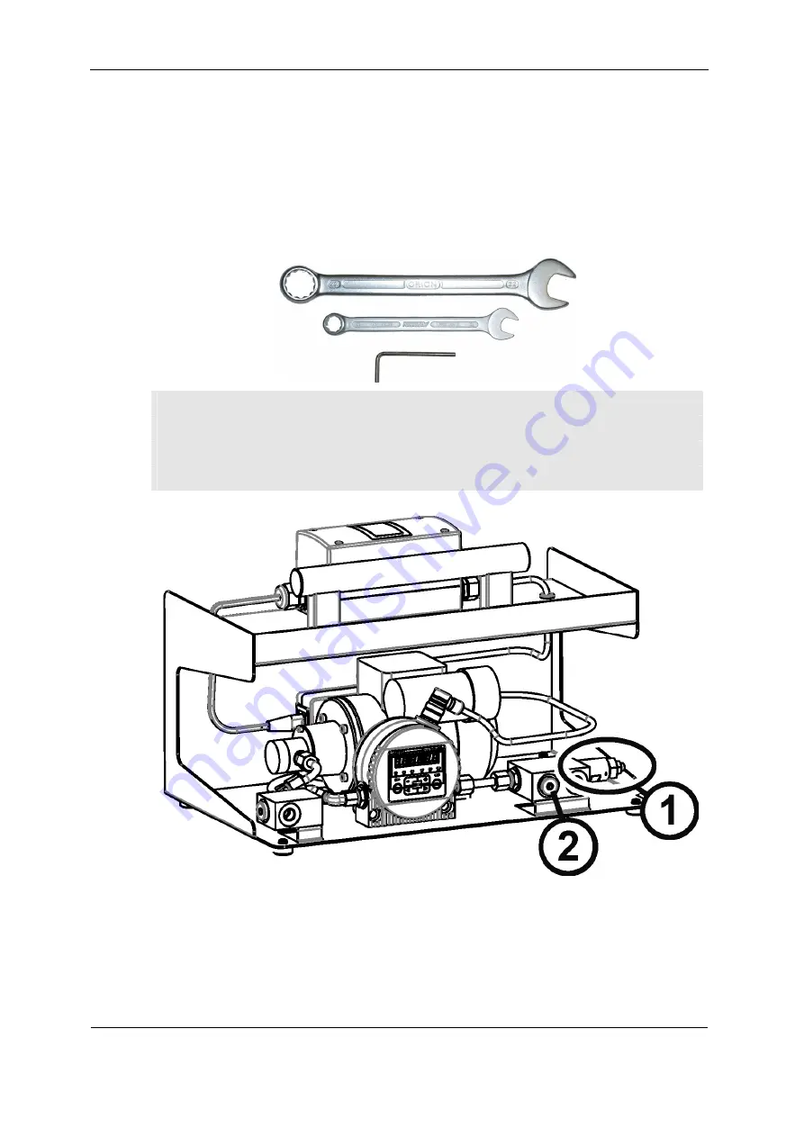
Adjusting the counter balance valve


Adjusting the counter balance valve 

The counter balance valve is set to 8 bar at the time the unit is shipped. Correct this 
setting in exceptional cases only. 


Required tools and measuring instruments 


Combination wrench, size 22 mm 

Combination wrench, size 13 mm 

 Allen wrench, size 4 mm 

 Allen wrench, size 6 mm 


HYDAC FILTER SYSTEMS GMBH 

en(us) 

Page 25 / 36

BeWa CMP1321 3765034 en 2012-09-25.doc 

2012-09-25


Summary of Contents for CMP 1321

Page 1: ...CMP 1321 ConditionMonitoring Package Operating and Maintenance Instructions English translation of original instructions Document No 3765034 ...

Page 2: ...rnational GmbH Industriegebiet 66280 Sulzbach Saar Telephone 49 0 6897 509 1511 Telefax 49 0 6897 509 1394 E Mail guenter harge hydac com HYDAC FILTER SYSTEMS GMBH All rights reserved No part of this work may be reproduced in any form print photocopy or by other means or processed duplicated or distributed using electronic systems without the written consent of the publisher These documents have b...

Page 3: ...ions 10 Training and Instruction of Personnel 11 Safety Measures to Be Followed during Normal Operation 12 Electrical Hazards 12 Dangers by pressure in the hydraulic system 12 CMP modification 12 Packing storage 13 Unpacking 13 Storing the CMP 13 Checking the scope of delivery 14 CMP Features 15 Restrictions pertaining to use 15 CMP Components 16 CMP hydraulic diagram 17 CMP dimensions 18 Hydrauli...

Page 4: ... doc 2012 09 25 Starting up the CMP 24 Adjusting the counter balance valve 25 Required tools and measuring instruments 25 Performing maintenance 29 Clean the suction strainer 30 Disposing of the CMP 31 Errors and troubleshooting 32 Customer Service 32 Spare parts list 33 Technical data 34 ...

Page 5: ...he information on the unit s engineering contained in the documentation was that available at the time of publication Consequently there might be deviations in technical details illustrations and dimensions If you discover errors while reading the documentation or have suggestions or other useful information please don t hesitate to contact us HYDAC FILTER SYSTEMS GMBH Technische Dokumentation Pos...

Page 6: ... to the product e g purchasing options etc may result in the information in the operating instructions no longer being completely accurate or sufficient When making modifications or performing repair work to components affecting the safety of the product the product may not be put back into operation until it has been examined and released by a HYDAC representative Please notify us immediately of ...

Page 7: ...ing for The document has a table of contents at the beginning I select the chapter I m looking for and the corresponding page number de HYDAC Filtertechnik GmbH BeWa 123456a de Seite x Produkt Kapitel 200x xx xx Chapter Page number Edition date Document language Documentation No with Index File name The documentation number with its index enables you to order another copy of the operating and main...

Page 8: ...gnized safety regulations Nevertheless hazards may be posed to the life and limb of the individual using the product or to third parties Risk of damage may be posed to the product or other equipment and property Use the CSM solely for its designated use only when in a safe perfect condition Immediately remedy any malfunctions that might impair safety Our General Terms and Conditions apply They are...

Page 9: ... CMP was developed for the continuous monitoring of solid particle contamination in hydraulic systems Any other uses shall be deemed to be improper and not in keeping with the product s designated use The manufacturer will not assume any liability for any damage resulting from such use Proper or designated use of the product extends to the following Maintaining adherence to all the instructions co...

Page 10: ...cinity of the product In addition to the operating instructions the general and local regulations on accident prevention and environmental protection are to be made available and observed All safety guidelines and hazard warnings on the machine must be maintained in legible condition and replaced as required The hoses and connection fittings are to be checked daily for leakage visual check The ele...

Page 11: ... undergoing training may not use the CMP unless supervised by an experienced staff member Individuals Individuals undergoing training Individuals with technical training engineering background Electricians Supervisor with the appropriate authority Activity Packing transportation X X X Commissioning X X X Operation X X X X Troubleshooting locating the source of malfunction X X X Troubleshooting mec...

Page 12: ...ydraulic system WARNING Hydraulic systems are under pressure Danger of bodily injury The hydraulic system must be depressurized before performing any work on the hydraulic system CMP modification Do not make any modifications design modifications extensions to the CMP without the prior consent of the manufacturer Immediately replace any unit components which are not in perfect condition Use only o...

Page 13: ...re closed off so that no contamination can enter the unit while it is in transit When receiving and unpacking the unit check it for damage in transit Dispose of the packing material as specified by law or national regulations or recycle it Storing the CMP Make sure to store the CSM in a clean dry place The unit is to be drained completely before being put into extended storage The maximum storage ...

Page 14: ...P into operation unless it is in perfect condition Report any damages in transit to the transport company or the responsible agent immediately Do not put the unit into operation The following items are included in the scope of delivery Item Qty Designation 1 1 CMP 1 Technical Documentation const of Operating and Maintenance Instructions CMP Operating and Maintenance Instructions CS 1000 series Cal...

Page 15: ...e measurement results are not skewed or only minimally impacted Because fluid absorbs an increasing quantity of air as the pressure increases rule of thumb 8 air per bar the ContaminationSensor aims to achieve the greatest possible pressure This is done using a downstream pressure relief valve However pressurized air cannot be immediately dissolved in the fluid consequently a path is provided for ...

Page 16: ...pump with integrated pressure relief valve 3 Counter balance valve 4 ContaminationSensor CS1000 series 5 Suction screen 400 µm 6 Suction port connection IN 7 Return port connection OUT HYDAC FILTER SYSTEMS GMBH en us Page 16 36 BeWa CMP1321 3765034 en 2012 09 25 doc 2012 09 25 ...

Page 17: ... Electric motor 2 Gear pump with integrated pressure relief valve 3 Counter balance valve 4 ContaminationSensor CS1000 series 5 Suction screen 400 µm 6 Suction port connection IN 7 Return port connection OUT HYDAC FILTER SYSTEMS GMBH en us Page 17 36 BeWa CMP1321 3765034 en 2012 09 25 doc 2012 09 25 ...

Page 18: ...CMP CMP dimensions CMP dimensions HYDAC FILTER SYSTEMS GMBH en us Page 18 36 BeWa CMP1321 3765034 en 2012 09 25 doc 2012 09 25 ...

Page 19: ...nection of the CMP Hydraulic connection of the CMP Hydraulic connectors IN Suction port connection OUT Return port connection HYDAC FILTER SYSTEMS GMBH en us Page 19 36 BeWa CMP1321 3765034 en 2012 09 25 doc 2012 09 25 ...

Page 20: ...nsity kg dm Mineral oil based hydraulic fluid has a density of 0 9 kg cm This applies to straight pipe runs and hydraulic oils Additional threaded connections and pipe bends increase the pressure differential Keep the height difference between the unit and the oil level in the tank as low as possible Hoses must be suitable for suction pressures of at least 0 5 bar Constrictions in the connections ...

Page 21: ...t be 8 10 mm in order to prevent excessively high pressure loss Suction connection to the tank must be made so that it is always below the oil level NOTICE Contamination too high The unit will be damaged Do not prime directly at the bottom of the tank Do not prime in the sump Never prime without a built in suction screen The greatest contamination is found on the bottom of the tank All impurities ...

Page 22: ...age 22 36 BeWa CMP1321 3765034 en 2012 09 25 doc 2012 09 25 Return port connection OUT NOTICE Return port connection OUT closed off The unit will be destroyed Make sure that the return port is always open Note the maximum pressure of 0 5 bar at the return port connection ...

Page 23: ...electrical equipment may only be done by a properly trained certified electrician Compare the voltage and frequency specifications on the type label with the specifications for the available network Plug the power plug into a suitable power outlet HYDAC FILTER SYSTEMS GMBH en us Page 23 36 BeWa CMP1321 3765034 en 2012 09 25 doc 2012 09 25 ...

Page 24: ...ta using an HMG3000 Starting up the CMP Prerequisite for commissioning is that the CMP is connected hydraulically to the entire system via IN OUT and that the electrical power supply has been established Switch on the CMP at the main switch The counter balance valve is set to 8 bar at the time the unit is shipped HYDAC FILTER SYSTEMS GMBH en us Page 24 36 BeWa CMP1321 3765034 en 2012 09 25 doc 201...

Page 25: ... at the time the unit is shipped Correct this setting in exceptional cases only Required tools and measuring instruments Combination wrench size 22 mm Combination wrench size 13 mm Allen wrench size 4 mm Allen wrench size 6 mm HYDAC FILTER SYSTEMS GMBH en us Page 25 36 BeWa CMP1321 3765034 en 2012 09 25 doc 2012 09 25 ...

Page 26: ... 3 Check the suction intake characteristic of the pump and the flow rate 4 If a uniform volume flow can be heard via the noise of the pump or if it can be detected on the outlet side OUT the pressure gauge will display the pressure at the outlet on the ContaminationSensor CS1000 5 Unscrew the head nut from the counter balance valve 1 6 Release the lock nut on the counter balance valve 1 HYDAC FILT...

Page 27: ...tment screw on the counter balance valve 1 8 Tighten the lock nut Make sure that the setting of the counter balance valve 1 is not changed in the process 9 Screw the head nut onto the counter balance valve and tighten it firmly HYDAC FILTER SYSTEMS GMBH en us Page 27 36 BeWa CMP1321 3765034 en 2012 09 25 doc 2012 09 25 ...

Page 28: ...DAC FILTER SYSTEMS GMBH en us Page 28 36 BeWa CMP1321 3765034 en 2012 09 25 doc 2012 09 25 10 The CMP is now ready for operation 11 Switch off the CMP at the main switch 12 Remove the pressure gauge from port 2 and seal it using the screw plug ...

Page 29: ...ly and protected against being inadvertently switched back on when performing any maintenance servicing inspection or repair work Once maintenance work is complete check that the safety devices are still working properly Any screwed fittings which have been undone removed are to be checked to see that they have been properly resecured 24 hrs or daily 500 hrs or monthly 3000 hrs or twice per year C...

Page 30: ...piece of pipe of the suction line to protect the pump from coarse contamination Check the suction strainer immediately in the event of insufficient suction or delivery action To replace the suction strainer proceed as follows 1 Open the screw plug using a size 6 Allen wrench 2 Take out the suction strainer by rotating it with a large flat screwdriver in counterclockwise direction HYDAC FILTER SYST...

Page 31: ...a large flat screwdriver 5 Screw in the screw plug by hand and tighten it with 12 Nm Disposing of the CMP Dispose of the packaging material in an environmentally friendly manner After dismantling the unit and separating the various materials dispose of the unit in an environmentally friendly manner HYDAC FILTER SYSTEMS GMBH en us Page 31 36 BeWa CMP1321 3765034 en 2012 09 25 doc 2012 09 25 ...

Page 32: ...n the shut off device Suction strainer is clogged Clean the suction strainer No flow The coupling between the motor and the pump is loose or faulty Check the coupling for proper functioning No function Not connected to power supply Check the electrical connection the plug cables and socket on the CMP For CS1000 error messages refer to the corresponding chapter in your CS1000 operating and maintena...

Page 33: ... 33 36 BeWa CMP1321 3765034 en 2012 09 25 doc 2012 09 25 Spare parts list Item Part no Qty Description Material 3152786 1 Suction screen 400 µm 1 ContaminationSensor CS 1000 3281243 1 Connection socket M12x1 8 pin 1 Motor pump assembly EPDM Teflon on request ...

Page 34: ... pressure at suction port connection IN 0 9 bar 50 bar Pressure at return port connection OUT 0 5 bar max Pump type Gear pump Max suction height 500 mm Sealing material EPDM Teflon Suction port connection IN G Return port connection OUT G Permissible operating viscosity range 1 100 mm s Permissible viscosity range for the measurement operation 1 50 mm s Total flow 200 ml min Electrical data Voltag...

Page 35: ...Notes ...

Page 36: ...iet Postfach 1251 66280 Sulzbach Saar 66273 Sulzbach Saar Germany Germany Phone 49 0 6897 509 01 Central Fax 49 0 6897 509 846 Technical Department Fax 49 0 6897 509 577 Sales Department Internet www hydac com E Mail filtersystems hydac com ...

Reviews: