Final Assembly
( ) Place 7/16" caplug on each element tip and a 2" caplug on each end of the boom.
Wind an RF choke using RG-8/u coaxial cable as shown in Figure 6. This choke must
consist of 13 turns with a 5" diameter. Strip one end of the choke as shown in Figure 6
and connect to the tubing clamps on the Driven Element. Tape the choke securely to
the boom and weatherproof the connection to the Driven Element using Pli-O-Bond,
Neoprene, or some similar substance. Also, tape the coaxial braid to prevent it from
shorting out on the element bracket or the boom. A choke is necessary to keep
unbalanced currents from flowing down the coax and decreasing the efficiency of the
NOTE: In place. of the RF choke it is recommended that you obtain a Hy-Gain balun,
Model BN-86, available at your local Hy-Gain dealer. The BN-86 allows the
DB-1015A
to operate with an efficiency greater than is possible with a "homemade" choke.
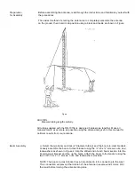
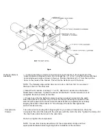
( ) Your DB-1015A is now ready to be installed on a 1 5/8” O.D. mast. Use one of the
methods explained at the beginning of this section. When mounting the completed
antenna, be certain to pin the bracket to the mast as explained in the section' "Boom
Assembly." Tape the coaxial feedline to the mast every 6" using waterproof tape.
( ) For lightning protection and noise free reception' ground the base of your tower.
Use an 8' copper clad, steel ground rod driven into the ground as close to the base of
the tower as possible. Attach the tower to the ground rod using #8 or larger copoer or
aluminum wire. for total protection of your equipment from lightning it is recommended
that you obtain a Hy-Gain Model LA-1, lightning arrestor.
This completes the installation of your DB-1015A. Happy DX'ing.


