background image


19 


Cover  the  whole  torch  cable  (from  torch  holder  to  output  terminal  )  of  the 

cutter with shielding layer, the shielding layer should be metal hose or shielding 

net  pipe  made  of  aluminum  or  copper,  metal  materials  which  is  magnetic 

conducted  cannot  be  used,  the  shielding  layer  don't  need  to  connect  with 

ground; 


All  the  control  lines  which  connected  with  plasma  power  source  should  be 

shielding wire, the shielding layer should be connected ground well; 


The  control  system  of  CNC  cutting  machine  should  be  away  from  the  cutting 

table,  torch  cables  and  cutting  torch  head,  especially  the  cutting  torch  heard. 

When striking arc, the high frequency spark arc on the cutting torch head may 

produce strong space spreading high frequency disturb signal, which may crash 

the control system; 


There  should  be  shields  on  the  controller  of  CNC  system,  and  the  shielding 

layers should be ground connected well;   


All the lines connected with CNC controller and cutting table should be shielding 

wire (Such as the control wire of step motor ,limit switch etc.), and the shielding 

layers should be ground connected well; 


The pile of the ground cable should be connected with ground well. 


6.12


Operation   

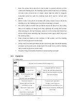
1)


Safety note 


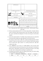
Notes: 

Operation strictly accordant with the following steps 


Notice 

Electric shock may hurt 

or even kill man. 


Cutting may cause fire or explosion 

(Splashes may ignite flammable materials 

nearby. Those materials should be 10m away 

from the working place.   

(Shut off the power during 

connection 

(Do not touch the conducted parts 


Fume & dust is harmful. 

(Do not breathe in the fume and 

dust caused by cutting 

(Clean up the oil spot on work 

piece. 

(Keep fresh air in working place 

(Fume extraction equipment 


Arc may hurt your eyes and skin. 

(Strong arc may hurt your eyes. 

(Ultraviolet radiation generated by arc may 

hurt skin and eyes. Please wear shielded guard 

when cutting. 

Summary of Contents for LGK-120HD

Page 1: ...LGK 120 200 300 400HD AIR PLASMA CUTTING MACHINE MANUAL INSTRUCTION PLEASE READ IT CAREFULLY BEFORE OPERATION ...

Page 2: ...es of cutter is IP21S so working in rain is not suitable 4 The cutter has external static characteristic with rated duty cycle 100 which means the machine can work continuously at the rated cutting current The machine has the function of thermal protection When the internal temperature exceeds a set temperature thermal protection moves on and the abnormity indicator lamp on the panel turns ON then...

Page 3: ...ater for cooling Never touch electric components of two welding machines at the same time because this voltage is supposed to be two times of welding voltage while the grounding mode is not clear While working high above the ground or other places having the risk of falling please be sure to wear safety belt to avoid losing balance caused by electric shock 2 Arc Use an arc welding mask to protect ...

Page 4: ...le installing the decompression flow meter or the gasometer When not working please tighten the valve 6 Power For electrically powered welding and cutting equipment Turn off input power before installation maintenances and repair so that avoid accident HUAYUAN welding equipment is Ι class safeguard equipment please install the equipment in accordance with the manufacturer s recommendations by spec...

Page 5: ...supplied by HUAYUAN There is no lifting equipment in its wrapper Users can move it to the prospective area by a fork lift truck and then open the box If having rings the machine can be transited using rings While HUAYUAN Welding Machine Manufacture reminds users there is possible risk to damage the welding machine It is better to push the welding machine moving in use of its rollers unless special...

Page 6: ... PRESSURE REGULATING FILTER THE FUNCTION OF PRESSURE REGULATING FILTER PLEASE CHECK THE BELOW FIGURE 9 6 6 CONNECTION OF COOLING WATER LGK 120HD DOES NOT HAVE THIS FUNCTION 9 6 7 THE CONNECTION OF OUTPUT TERMINAL 10 6 8 THE CONNECTION OF CONTROL SIGNAL CONNECTORS FOR CNC AUTOMATIC CUTTING CONNECTION 11 6 9 THE CONNECTION OF WATER COOLING MACHINE INTELLIGENT COMMUNICATION INTERFACE THERE IS NO THIS...

Page 7: ... ELIMINATING ISSUE 26 8 3 CUTTING TABLE 28 9 PACKING LIST 34 9 1 PACKING LIST OF PLASMA POWER SOURCE 34 9 2 SYSTEM PACKING LIST 34 10 MAINTENANCE 34 11 TROUBLESHOOTING 35 11 1 PLEASE FIRSTLY CHECK FOLLOWING ITEMS IF ANY TROUBLES 35 11 2 ORDINARY TROUBLESHOOTING AS FOLLOWING SHEET 36 11 3 SOME POPULAR COMPONENTS SHEET AS BELOW 37 12 ATTACHED DIAGRAM 1 MAIN CIRCUIT DIAGRAM 39 ...

Page 8: ...an be separately set according to the torch cable length The plasma gas pressure can be adjusted on the panel the pressure is displayed on the meter friendly operation There is digital communication connector can be connected with different automation equipment With torch monitoring function warning to change the consumables to longer the torch working life Intelligent fan is used to reduce the du...

Page 9: ...ncrease Decrease The nozzle connection of plasma torch Plasma gas and torch electrode Current Coolant liquid and torch electrode 2 Safety and attention Please follow the notes for the safety of you and others It is forbidden to unfreeze the pipe line by cutting power or other usages except for cutting The cutter casing should ground reliably Please make sure the grounding bolts of power ground rel...

Page 10: ...d protect the cable from sharp materials Protect the machine from fall or collision In case of fall or collision it can be used only after professional checking In the surface or inside of the cutting work piece there should be no flammable and explosive materials or chemical materials harmful to human Installation and repair person must have state authorized electrician operation certificate Cutt...

Page 11: ...alcutting 0 3 25mm 1 45mm 1 50mm 1 60mm Max CuttingThickness Carbonsteel manualcutting 45mm 65mm 80mm 90mm Plasma gas Compressed Air The working plasma gas pressure 0 3 0 5MPa 0 4 0 6MPa 0 4 0 6MPa 0 4 0 6MPa Torch cooling mode Air Cooling Air Cooling Water Cooling Arc striking mode HF Insulation grade F Protection grade IP21S Dimension mm L W H 675 320 605 863 385 800 985 445 910 1015 445 910 NET...

Page 12: ...r and the output cutting current is obtained Control circuit can control output current by controlling driven pulse width The real time cutting current which is obtained through current sensor connected to output terminal in series is used as negative feedback control signal After comparing with current adjusting signal the negative control signal is sent to PWM adjusting integrated circuit then a...

Page 13: ...or upended When lifting it must be lifted vertically During the long distance transportation it must prevent the cutter from raining and moving back and forth inside box Shock absorption foam should be placed around cutter 6 2 Open the packing and check 1 Check the machine and packing according to the packing list of there is any damage please try to contact the supplier 6 3 The fix and installati...

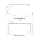
Page 14: ...7 LGK 120HD Dimension and installation size LGK 200HD Dimension and installation size ...

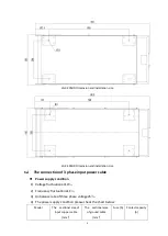
Page 15: ...hase input power cable Power supply condition 1 Voltage fluctuation 10 2 Frequency fluctuation 1 3 Unbalance rate of three phase voltage 5 4 The power supply condition please check the chart below Model The sectional area of input copper cable mm2 The sectional area of ground cable mm2 Fuse A Contact capacity A ...

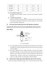
Page 16: ...below figure Pic 7 Air filter regulator 1 The compressed gas should meet the requirement mentioned in point 4 2 Plasma gas conditions Connect the gas pipe with the gas inlet of air filter on the rear panel and hoop it tightly 2 The air filter regulator should be checked periodically If the water level reaches two thirds of filter glass it must be drained or the cutting incision quality will be eff...

Page 17: ...When use air cooling torch short connect the pin 3 and 4 when use water cooling torch don t connect the pin 3 and 4 Air Current output the negative output connector of the machine is the plasma gas output connector the connector thread is M14 1 5 Water Current output the negative output connector of the machine is the cooling water output connector to connect the water inlet of the water cooling t...

Page 18: ...uirements of control plug connection when customers use different torches Use WS20J4TQ 4 pins plug Requirements on air cooling torch connection a Connect the 1 2 pin of 4 pins plug to switch control wire of cutting torch b Short connect 3 4 pin of 4 pins plug by gummed wire c Pilot arc wire connects cold press joint UT 8 Requirements on water cooling torch a Connect the 1 2 pin of 4 pins plug to s...

Page 19: ...AC or 1A 30VDC 2 Connector pin 5 and pin 6 is protection signal that water cooling machine output to plasma cutter when short connect the pin 5 and 6 there will be no current and voltage output from the plasma cutter Special note To confirm the good cooling performance and lengthen the consumable life you d better choose the water cooling machine from HUAYUAN 6 10 Panel and it s function instructi...

Page 20: ...sure If this indicator light is ON means the plasma gas pressure 0 38MPa it s normal The indicator light 0 3s on and 0 3s off Quick flashing means the plasma gas pressure is in warning value range 0 3MPa air pressure 0 38MPa now the cutter can work but the cutting quality may get bad and the consumables may burned faster The indicator light is off means the plasma gas pressure 0 3MPa now the cutte...

Page 21: ...NPUT FAULT indicator light when the power supply is lower than 280VAC this indicator start flashing 0 3s on and 0 3s off and stop working After the power input back to normal the indicator light will slow flash and start to work again 15 AIR CHECKING indicator light when this indicator is on mean it s on air checking status 16 AIR CHECKING key press this key and the indicator light will on No 15 n...

Page 22: ... To control automatic cutting equipment there is starting signal and arc striking success signal Pin 1 and 2 is pilot arc signal output it s a group of relay contact inside after striking the arc the contact closed can control the load with rated loading capacity of 5A 250VAC or 5A 30VDC Pin 3 and 4 is starting signal the starting mode please check No 4 25 Intelligent communication connector of wa...

Page 23: ...ber wire to connect the wire terminal on printed board PL13 Please connect the wire according to the requirements and pay attention to the negative and positive electrode This signal is not insulated please make sure there is no any of potential relationship between the connected equipment and the cutter 27 Fuse holder of arc voltage signal 28 The power input connecting box to connect the 3 phase ...

Page 24: ...oling machine from the torch 34 The torch connection instruction 35 SHEET METAL cutting function indicator light Only on LGK 120HD Press WORKPIECE key when the indicator is on if the plasma arc stop during cutting process the cutter will not work anymore until get a new starting signal this function is for normal cutting 36 MESH METAL cutting function indicator light Only on LGK 120HD Press WORKPI...

Page 25: ...g arc will extinguish automatically Note When adjust the air pressure the panel function must be set to GAS TEST 2 Water pressure protection LGK 120HD does not have this function When the water supply flow is lower than 2L min the COOLANT FLOW indicator light will not on if press the torch switch 0 9S the water flow still lower than 20 L min protection circuit starts working and cutter cannot star...

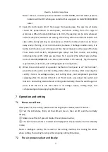
Page 26: ... CNC system and the shielding layers should be ground connected well All the lines connected with CNC controller and cutting table should be shielding wire Such as the control wire of step motor limit switch etc and the shielding layers should be ground connected well The pile of the ground cable should be connected with ground well 6 12 Operation 1 Safety note Notes Operation strictly accordant w...

Page 27: ...he lamp will be OFF a error code E80 will be displayed on the meter then the gas source should be checked 3 Start water supply equipment The indicator lamp of water pressure on panel is ON when opens water supply valve LGK 120HD does not have this function 4 Place the gas control switch to GAS TEST adjust the Adjusting knob of air filter regulator to make the output pressure and flux fit cutting c...

Page 28: ...second high frequency is generated arc is stroke and cutting begins by moving torch 8 When the control switch of operation method on front panel is at Torch Unlock press the torch switch and the cutting starts after arc striking After loosening the switch there is no voltage output and cutting stops and compressed gas stops supplying after 10 seconds When it is at Torch Lock press down the switch ...

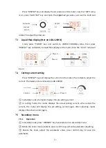
Page 29: ...otate to adjust the current The below picture is based on LGK 200HD In standby mode the meter displays the pre setting current In cutting mode the meter displays the actual cutting current when adjust the current the meter will display the pre setting current again after adjusting meter displays the actual current again 7 5 Secondary menu 7 5 1 Operation In standby mode press OPERATE key 5 seconds...

Page 30: ... controlling cutting stops P05 Piercing time set 1 999 Time 999 P06 Cutting rest time disp Min P07 Piercing rest time disp Time P08 Monitor control switch 0 or 1 0 On 1 Cannot cut after warning Off 0 Can cut after warning P09 Monitor parameter reset Reset 1 Keep 0 0 1 means reset immediately the cutting time and arc striking time rest P10 Monitor warning function On 1 off 0 0 To open close the tor...

Page 31: ... P04 cutting time set and P05 piercing time set set a suitable value according to the working life of nozzle and electrode Step 3 enter secondary menu and choose P08 monitoring control switch set the value to 1 and press confirm key then the cutting will be stopped after warning if set the value to 0 then only the warning information will be displayed the machine can keep working Step 4 enter seco...

Page 32: ... and quality is improved accordingly Because the arc compression level increases the energy is more concentrated the arc beam temperature the arc spraying speed as well as the arc current impulsion increases But overlarge current may cause the instability of the plasma arc Usually no change is made to air flow for one torch But it can be adjusted a little when the cutting torch or cutting thicknes...

Page 33: ...loy steel have bad thermal conductivity the incision bottom is over heated easily the left molten metal and incision bottom melts into one thereby the irremovable and tough burr is formed On the contrary when cut copper or aluminum the incision bottom is difficult to be melted together with molten metal and the burr formed under incision is come off easily 2 The factors affecting the forming of bu...

Page 34: ...ration of flame and cutting capacity can be guaranteed Enough power to ensure the fluidity of molten metal as well as increase the stability of the cutting speed and operation This makes it possible to adopt large air flux to enlarge the air blow force and beneficial for eliminating burr Adjust suitable air flow and cutting speed If the air flow is too small the blow force is not enough while if t...

Page 35: ...ng materials user should adjust it as actual condition Cut from edge unless you have to make a piercing Choose suitable consumables according to different cutting technology When change the consumables power have to be off and use the equipped torch use wrench The values in the cutting table below is based on System components in this operation manual it s a useful reference for some cutting condi...

Page 36: ...500 11 2 30 7 5 168 1200 2 5 0 52 32 8 5 172 900 12 0 57 35 9 5 175 650 Cut from edge 38 180 600 0 60 50 10 198 300 The gas pressure in this table is the gas pressure that displayed on the plasma power source panel when cutting The values in the table is based on the plasma working with Huayuan water cooler ...

Page 37: ...age Cutting speed Initial piercing height Piercing time Pressure Mpa mm mm V mm min mm s 0 47 8 1 3 128 4000 5 0 4 12 1 7 135 3000 6 0 5 0 49 16 2 137 2100 8 20 4 150 1600 9 0 8 25 5 158 1300 11 1 2 0 50 30 8 170 1000 12 1 2 0 57 35 8 177 700 Cut from edge 0 58 38 8 5 184 600 0 60 50 9 200 300 The gas pressure in this table is the gas pressure that displayed on the plasma power source panel when c...

Page 38: ...ork piece Arc voltage Cutting speed Initial piercing height Piercing time Pressure Mpa mm mm V mm min mm s 0 47 8 2 137 3000 5 0 5 12 2 139 2500 5 0 8 0 49 16 4 150 1800 8 1 20 4 152 1200 8 1 2 25 5 5 162 950 11 1 5 0 50 30 5 5 166 650 Cut from edge 32 6 168 500 50 7 185 200 The gas pressure in this table is the gas pressure that displayed on the plasma power source panel when cutting The values i...

Page 39: ...h and work piece Arc voltage Cutting speed Initial piercing height Piercing time Pressure Mpa mm mm V mm min mm s 0 47 6 2 145 3300 4 0 4 8 2 5 147 2800 5 0 5 0 50 12 3 155 2300 6 0 6 16 3 5 160 1500 7 0 7 20 4 165 1000 8 0 9 25 4 5 172 700 Cut from edge 30 4 5 178 450 The gas pressure in this table is the gas pressure that displayed on the plasma power source panel when cutting The values in the ...

Page 40: ...een torch and work piece Arc voltage Cutting speed Initial piercing height Piercing time Pressure Mpa mm mm V mm min mm s 0 45 4 2 140 4400 4 0 4 6 2 145 3100 4 0 4 8 3 150 2200 6 0 6 10 3 155 1800 6 0 8 12 3 160 1300 6 1 16 4 168 800 Cut from edge 20 4 178 450 The gas pressure in this table is the gas pressure that displayed on the plasma power source panel when cutting The values in the table is...

Page 41: ...e and store it in a well ventilated working environment 5 Open and clear inside the machine with dry compressed air at least once a year to clear the dust and metal filing 6 Check the insulation of all cables regularly repair or change it if any damages Check the insulation of all connections inside the machine tighten it if any loosen 7 Discharge the water and impurities in the filter regularly 8...

Page 42: ...oned in instruction manual 5 Check if the cutting ground cable is well connected 6 Check if the water in compressed air filter fixed at the back of machine is drained regularly 7 Check if the gas pressure indicator lamp on the panel is ON If it is not ON check if compressed gas pipe is well connected and if the gas pressure is normal When the gas pressure is less than 0 3Mpa the lamp is not ON whe...

Page 43: ...Cut off the power and change the consumables please refer to 7 6 torch monitoring function 3 No arc striking or arc breaking during cutting Overheat indicator lamp is ON 1 The ambient temperature is too high 2 When cutting cooling fan rotates slowly or do not rotate so the cooling effect is weak 3 Temperature relay is damaged 1 Let the cutter rest for a while and will come to work normally later 2...

Page 44: ...utter output circuit 1 Change fast recovery diode under same model 2 Check and change the damaged frequency board PL13 3 Check leakage point and strengthen insulation function Supply power trips 1 Three phases rectifier is damaged 2 IGBT module is damaged 3 Other components in main control circuit is damaged 1 Change a three phases rectifier under same model 2 Change IGBT module under same model 3...

Page 45: ...0HD KT1 KT2 KT3 LGK 300 400HD 10 Gas pressure sensor IP11C BP1 11 Liquid flow sensor SEN HZ21WI BP2 12 Control board PL12 AP1 13 Driving board PT05 10Ω AP2 14 High frequency board HFAP1 AP3 15 Arc striking board PL13 AP4 16 Panel PL15 AP5 LGK 120HD PL14 LGK 200 300 400HD 17 Gas filter GF20008W LGK 120HD GF30010 LGK 200 300 400HD Sheet 7 Popular components list ...

Page 46: ...5 c 3 6 a 3 4 a 3 3 a 3 5 a 2 7 2 4 1 5 V 1 Out 3 15V 2 0 V 4 TA2 R V 2 R 5 2 7 R 6 R 7 2 3 1 4 5 C 8 C15 FU1 1 A G N D W D G D 1 5 V 15V 3 6 b 3 4 b 3 3 b 3 5 b L 1 C 4 A 1 C 2 B 3 EC11 XZ1 AP2 TM1 1 1 0 V 0 V 2 1 5 V 3 8 0 V 4 1 5 V G N D W D G D 1 5 V 15V 温 控 给 定 50 1 100 1 B P 1 P AP1 AP3 3 6 V L 6 0 V 7 8 1 9 2 0 2 1 2 2 7 9 8 0 3 0 3 1 3 2 0 3 7 3 8 4 0 3 9 7 1 7 2 7 3 7 4 6 9 7 0 4 3 4 4 4 ...

Page 47: ... 5 2 7 R10 R11 2 3 1 4 5 C 8 C26 FU1 1 A G N D W D G D 1 5 V 15V 3 6 b 3 4 b 3 3 b 3 5 b L 1 C 4 A 1 C 2 B 3 EC11 XZ1 AP2 TM1 1 1 0 V 0 V 2 1 5 V 3 8 0 V 4 1 5 V G N D W D G D 1 5 V 15V 50 1 100 1 B P 1 P AP1 AP3 3 6 V L 6 0 V 7 8 1 9 2 0 2 1 2 2 7 9 8 0 3 0 3 1 3 2 0 3 7 3 8 4 0 3 9 7 1 7 2 7 3 7 4 6 9 7 0 4 3 4 4 4 5 8 3 8 4 8 5 4 9 5 0 5 1 5 2 5 3 5 4 5 5 5 6 5 7 5 8 6 8 9 0 6 3 6 4 6 5 6 6 8 6...

Page 48: ...15V Q Y C12 R 4 L 3 C11 R 3 G a G b G c G d E a E b E c E d TM1 1 1 0 V 0 V 2 1 5 V 3 8 0 V 4 1 5 V 3 6 V L 1 0 6 6 8 9 0 2 8 6 3 6 4 6 5 6 6 1 2 a 1 3 a 2 0 a 2 1 a 2 2 a 1 1 b 1 0 b 1 2 b 1 3 b 1 4 a 1 6 a 1 7 a 1 5 a 1 9 a 1 8 a 2 0 a 2 1 a 2 2 a 0 V AP1 AP2 XS6 1 2 3 4 XS2 1 2 9 5 9 6 XS4 2 1 4 3 XS2 2 1 XS4 R 6 Y V 2 Y V 1 A 1 C 2 B 3 EC11 XZ1 B P 1 P AP3 7 1 7 2 7 3 7 4 6 9 7 0 4 3 4 4 4 5 8...

Page 49: ...an Company If there is any changes in the user s manual forgive not to inform separately Chengdu Huayuan Electric equipment Co Ltd Address Wuhou National Science Park Chengdu China Postcode 610045 E mail hwayuansales 163 com Website www hwayuan com ...

Reviews: