5
4
4. STORAGE AND HANDLING
As a safety element, the fire damper must be stored, handled and installed carefully.
Pay attention to:
• unload in a dry area
• avoid any shocks
• do not use the damper as a workbench or scaffolding
• do not fit the small dampers in the large one
The damper must be stored in a dry place, and kept out of water and frost.
It should not be stacked beyond the original packaging.
It must be properly stowed so as to prevent any damage or deformation resulting from an impact or high humidity.
It must not be exposed to direct sunlight to prevent premature aging of the thermal fuse.
Once the damper is installed, the mechanism should be kept away from any projections (cement, paint, flocking, water,
dust) that may harm its operation.
The damper must be protected against the risk of heavy condensation.
The intumescent joints are essential for the fire resistance of the damper, all mechanical actions on the refractory parts
are to be excluded.
All precautions shall be taken to ensure that premature aging of the damper does not occur before it is actually in-
stalled.
The actions of wedging and caulking during the sealing of the dampers must not cause deformations that will alter the
good functioning of the damper and in particular the closing of the blade.
5. INSTALLATION AND IMPLEMENTATION
5.1 INSTALLATION:
• Mounting is possible with the blade axis in horizontal or in vertical position
• The installation must comply with the tests that were performed during certification, s explained in 8.2.
• Avoid any obstruction of the moving blade by the connected ducts
• The class of air-tightness is maintained in case the installation of the damper is made in accordance with the tech-
nical manual
• Operating temperature: 50° C max
• For indoor use only
The FD25 / FD40 fire damper is always tested in standardized support frames (both in a concrete wall and in a flexible
wall) in accordance with EN 1366-2: 1999 table 3/4/5. The results obtained are valid for all similar support frames which
have a thickness and / or density and / or fire resistance similar or greater than the one of the test.
5.2
INSTALLATION AND SEALING:
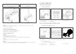
5.2.1 Concrete wall and reinforced concrete wall installation
The wall is composed of concrete blocks (minimum density of 550 kg/m3) and with a minimum thickness of 100 mm.
Place the damper in an opening of
Ø+
70 mm or more
Fix the damper to the wall using
screws
Fill the space between the damper
and the wall with mortar
5.2.2 Aerated concrete ceiling installation and reinforced concrete ceiling installation
The ceiling is made of aerated concrete with a minimum density of 550 kg/m3 and a minimum thickness of 100 mm.
Place the damper in an opening of
Ø+
70 mm or more
Fix the damper to the slab using
screws
Fill the space between the damper
and the slab with mortar
Summary of Contents for Klimaoprema FDC25
Page 12: ...23 22 NOTES...


