Huvitz SMART BLOCKER HBK-410 User Manual Download Page 94


94 


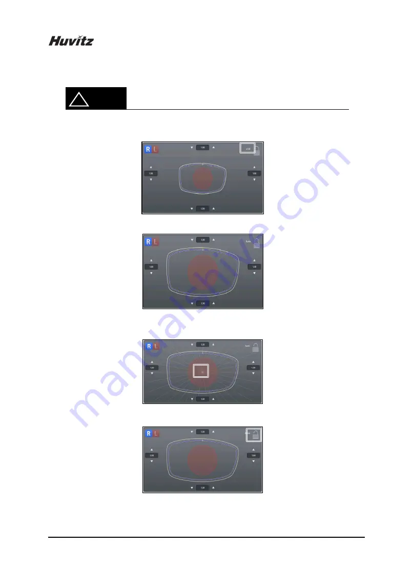
Touch the lens shape area, then the editing position moves to the touched area. 


To see the shape in actual size, press the upper right icon. 


[Actual measurement] 


[Auto – Shape resized to fit to the screen) 


Angle guideline pops up when you touch the center of the shape. (Guideline spacing - 10 °) 


Touch screen lock button (on/off) 


!


NOTE 

Touch Area 

Touch Area 

Touch Area 

Summary of Contents for SMART BLOCKER HBK-410

Page 1: ...SMART BLOCKER HBK 410 USER MANUAL...

Page 2: ...mes no responsibility however for possible errors or omissions or for any consequences resulting from the use of the information contained herein HUVITZ reserves the right to make changes in its produ...

Page 3: ...4 2 How to connect the device 17 5 Smart Blocker User Interface 19 5 1 Main Screen 19 5 1 1 Side Button 19 5 1 2 Job Management 22 5 1 3 Frame Information 24 5 1 4 Layout Option 24 5 1 5 Edging Optio...

Page 4: ...de 78 5 8 2 Partial Step Bevel Editing Area 78 5 8 3 Partial Step Bevel Option 81 5 8 4 Full Step Bevel Editing Area 82 5 8 5 Full Step Bevel Option 84 5 8 6 Fine Tuning 84 5 8 7 Preview 88 5 8 8 Curr...

Page 5: ...Fuse Replacement 114 7 9 2 Regular maintenance 114 7 9 3 Cleaning 114 8 Troubleshooting Guide 115 9 Specifications and Accessories 116 9 1 Standard Accessories 116 9 2 Specifications 116 9 3 Drawings...

Page 6: ...ent 9 7 LCD display and touch screen are harmonized to offer the actual size Frame PD and FPD etc display and the maximum convenience for everyday use User can design all information about layout and...

Page 7: ...pt any interference received including interference that may cause undesired operation Class A equipment Class A equipment is intended for use in an industrial environment In the documentation for the...

Page 8: ...ely within the text of this manual to highlight safety related information or information requiring special emphasis All users operators and maintainers must be familiar with and pay particular attent...

Page 9: ...symbol is attached to a product it means the product is covered by the European Directive 2002 96 EC Lorsque ce symbole de poubelle roulettes barr e est attach un produit cela signifie que le produit...

Page 10: ...exposed to water vapor Don t operate the machine with wet hands Indoor use only Where the machine is exposed to direct sunlight A place where the equipment can be exposed to direct ultraviolet Where t...

Page 11: ...y mains with protective earth This instrument must be followed by these following conditions Operation An ambient temperature range of 10 40 A relative humidity range of 30 90 An atmospheric pressure...

Page 12: ...TZ s service technicians or other authorized persons 5 Maintenance by users must observe the User s Manual and Service Manual Any additional maintenance may only be performed by HUVITZ s service techn...

Page 13: ...t there is the possibility of an explosion 17 To avoid the risk of electric shock this machine must only be connected to protective earth 18 Do not place the machine where it is difficult to operate t...

Page 14: ...e Otherwise it may cause the malfunction of the product Changes or modifications not expressly approved by the party responsible for compliance could void the user s authority to operate the equipment...

Page 15: ...stem Overview 3 1 Front View Display Touch Screen Lens Supporter Blocking Arm Reflector 3 2 Rear View SD card slot Power Switch Interface Terminal EDGER 1 EDGER 2 Barcode Reader Tracer Main Power Inpu...

Page 16: ...rter for Frame Change and Digital Scanning Touch Pen Please use genuine lens adaptor tape LEAP III Otherwise the lens axis may move We do not provide a sticker for Super Hydrophobic Lens but you shoul...

Page 17: ...the Power Cable into the socket at the rear side of the product and turn on the power If the initial indicator disappears and the main screen is shown on the LCD check if the touch screen is respondi...

Page 18: ...rocess is performed properly Read the frame from the frame reader and transfer the data to the blocker And then check the blocker is receiving the job data normally From the blocker open the job data...

Page 19: ...5 1 Main Screen 5 1 1 Side Button Press the R button to select right side Press the L button to select left side 5 1 2 Function Button Edging Option Lens Information Function Button Side Button Frame...

Page 20: ...are exchanged The other job options remain unchanged The function of exchange R L is useful when you selected wrong side while reading demo lens or patterns In addition to R L exchange R L shape mirr...

Page 21: ...OMA file extension should be oma Insert the SD card to the machine Press the L side button for a while Select the file and press the open button Some OMA files may not be fully compatible with our sy...

Page 22: ...n to load a new job or move on to another job Virtual Keyboard Use the virtual keyboard to change Job number Job number Backspace Apply Reset Cancel If you press the button the value goes back to orig...

Page 23: ...pend file extension such as oma or dxf at the end of Job Number you can export a job to OMA file or CAD file in the oma export or dxf export folder of the SD card eg 12345 oma You can request job from...

Page 24: ...lar PD value Monocular PD Input PD values for each side L R Bridge Size DBL Input value of bridge size FPD Input value of FPD OH Type Select one of three Y Box Height Mix Height OH Optical Height Inpu...

Page 25: ...Eye tracing it will be helpful to use Bridge Size Input function It is much easier to measure the Bridge Size Measure B not A for the Bridge Size Remember that the Bridge Size is not from frame to fra...

Page 26: ...olored yellow It changes into white when you input value If frame reader traces shape of frame for both side FPD value is calculated automatically Therefore input boxes of bridge size and FPD are disp...

Page 27: ...Numeric Keypad Click the value you want to change then this numeric keypad will pop up Name of the value Range of the value Value Increase Decrease Backspace Reset Cancel If you press it the value go...

Page 28: ...Bevel Semi U Bevel Available edging types can vary by wheel types of the edger Normal Type RPG RPW Asymmetric Type RPA RPGA Step Bevel edging type is available when the edger type setting is HPE 8000...

Page 29: ...l Asymmetric Bevel Semi U Bevel When the edger type setting is HPE 8000X or HPE 8000XN in the preference menu Bevel Height Editor is provided instead of Asymmetric Bevel Semi U Bevel height input NOTE...

Page 30: ...g Flat Grooving Hybrid Grooving Bevel Grooving Partial Bevel Bevel Flat Dual Grooving Relevant icon is displayed at edging type when partial grooving is selected To cancel the partial grooving mode pr...

Page 31: ...r mm Base Curve Auto Manual Size Adjustment 2 0 2 0mm Polishing Polishing Off Polishing On High Polishing Front Safety Beveling Safety Beveling Off Safety Beveling On Rear Safety Beveling Safety Bevel...

Page 32: ...ing Bevel Grooving and Partial Bevel Bevel Flat Lens Material Plastic Polycarbonate Hi Index Glass Trivex If the wheel type of the edger is Asymmetric or Wide Glass lens cannot be selected Glass lens...

Page 33: ...arked Bi focal Flat Bi focal Round Bi focal Curved Progressive Blocking Mode Optical Center Set blocking location to the optical center Boxing Center Set blocking location to the box center Frame Cent...

Page 34: ...ideline according to the lens type Press the guideline value box area and enter the value to change Normal lens Bi focal lens Progressive lens NOTE 1 1 1 2 Near vision area diameter 3 dot length Eye p...

Page 35: ...ance mm from the front side of the lens Distance mm from the rear side of the lens Adjust the position according to the lens base curve Auto mode Adjust the position manually Final outputs according t...

Page 36: ...Adjustment in advance Frequently used Adjustment Value can be saved at Frame Fitting in Configuration Menu Be sure to carry out the Edging Process in Safety Mode when the lens is fragile or the axis...

Page 37: ...7 HBK 410 5 1 7 Function Button Expert Job Editor Menu Digital Designer Digital Pattern Hole Editor Digital Scan Blocking The expert user can work more quickly by using Expert Job Editor 1 2 3 4 NOTE...

Page 38: ...38 5 2 Blocking Screen Press button on the main screen to enter blocking screen Blocking Mode Exit Layout Information Lens Type Brightness Control Zoom Rotation Send...

Page 39: ...eight Mix Height Blocking Mode You can enter PD OH value directly or fine tune with the buttons 5 2 2 Lens Type 3 dot marked lens Bi focal Lens Round Bi focal Lens Flat Bi focal Lens Curved Progressiv...

Page 40: ...d 5 2 3 Tool Button Brightness Control Low Brightness Control High Live Image Normal Zoom Reflector Rotation On Off 5 2 4 Sending Job Send Send the job data to the edger 5 2 5 Exit Quit the blocking s...

Page 41: ...n recognize the laser mark without any re marking on the lens If the laser mark is not clear adjust the contrast of the screen using and buttons HPE edger offers different types of lens adaptors When...

Page 42: ...tness manually Convert image file bmp jpg png or CAD File dxf to a job file Find hole slot in the digital scanning Set axis of demo lens manually by dragging the two points If there is no dragged line...

Page 43: ...After Digital Scan is done successfully frame shape is displayed in yellow color Otherwise the frame shape is displayed in red color Press the save button to save the scan result to Job Manager Copy i...

Page 44: ...lens is smaller than the frame Put size offset value for edging as much as the size difference and cut a lens If the lens fits bigger than the frame do retouch in the edger to make it smaller When th...

Page 45: ...45 HBK 410 5 4 Job Manager Job selection tab Exit Job list Function button...

Page 46: ...b Save Save the selected job to SD card Search Search Job number Delete Delete selected job Save function is only available on Waiting Working Completed list If the power of the system is turned off a...

Page 47: ...with icon Reading Displays the Tracing State with icon Frame Type Displays the Frame Type FPD Displays the FPD value DBL Displays the DBL value Time Displays the job received time 5 4 4 Working Job B...

Page 48: ...48 5 4 5 Completed Job Time Displays the job finish time You can check current processing state with the following icons 1 NOTE Waiting One side blocking completed Both sides blocking completed 1 2 3...

Page 49: ...5 4 6 Job Search You can search for a job on the job list Start Job Search Mode by pressing the search button Enter the job number you want with the virtual keyboard Check the list Search Button Enter...

Page 50: ...Number HUVITZ_123 only with HUVITZ or 123 You can look at the other research results with Next and Prev button You can finish the Job Search mode by pressing the search button one more time The search...

Page 51: ...itting for Rimless and Semi Rimless To use Digital Pattern press button on the bottom right of the main screen and then select the Digital Pattern tab at top left of the screen Enlargement Reduction N...

Page 52: ...of the 8 touch points around the lens shape Horizontal Vertical Horizontal Vertical Horizontal Vertical Horizontal Vertical Value Input You can modify the lens shape by entering the values directly i...

Page 53: ...duction Lens shape can be changed in four directions Bottom Near Vision Area Top Left Right Touch Interface To modify lens shape make use of 4 touch points around the lens shape Left or Right Top or B...

Page 54: ...e Input Area Left Right Near Vision Area Bottom Top After selecting the item to change enter the value using the numeric keypad 5 5 3 Rotation Lens shape can be rotated Touch Interface To rotate lens...

Page 55: ...can modify the lens shape by entering value directly in the Input Area Width Height Angle Clockwise 0 360 Function of and are same with that of Enlargement Reduction mode After selecting the item to...

Page 56: ...t on lens shape The point becomes the center of the modification area To adjust modification range touch and drag one of 2 touch points around the selected lens shape blue Range adjustment point Edit...

Page 57: ...ored red And when closing the digital pattern the shape can be modified to edging enabled shape intelligently The icon of end point changes to be enlarged when end point is positioned on the corner of...

Page 58: ...holding edit position change button 5 5 5 Toggle R L Sync Function for R L Sync R L Sync On R L Sync Off Copy button is available when R L sync option is turned off Shape of the current side is copie...

Page 59: ...e might cut out the near vision area In this case the digital pattern provides the enlargement of the frame shape When digital pattern is applied FPD or bridge size is recalculated according to the di...

Page 60: ...center of the frame box center If you add a slot or hole on the hole editor the blocking mode is changed to the center of the frame box center automatically In this case the blocking mode is fixed to...

Page 61: ...splayed on working area as you magnify the screen If you want to see other parts of the image please touch the red circle on preview Working Area Working area displays the shape of frame and holes slo...

Page 62: ...62 Elements required for drilling are displayed on working area The figure below describes each element NOTE Hole Frame Center Horz Coordinate Notch or Slot Vert Coordinate Undrillable area...

Page 63: ...zation of the right and left side can be turned on or off Properties or changes of the selected side are identically applied to the other side when the synchronization is on Preview You can see the sh...

Page 64: ...e on the LCD overlap to the frame shape on the camera image Hole Slot Easy Moving You can move the selected holes slots This function provides you precise movement Grouping You can select more than a...

Page 65: ...axis recognized When you press the Hole Slot Easy Moving button following screen will pop up You can use this to move the hole slot Select moving type You can select moving type When the selected one...

Page 66: ...are like below This provides the function of parallel movement The movement of hole slot is like below Hole Slot Slot only This provides the function to move the start position of a slot Slot only Thi...

Page 67: ...t will be moved to the edge of a frame close to current position and become a notch The slot can be moved with the notch remained by using the moving buttons The up and down buttons are for parallel m...

Page 68: ...onfiguration Load the hole slot data You can load the hole slot data from the SD card and include them to the current job a List of hole slot data This displays the list of hole slot data in SD card b...

Page 69: ...ot data to the current job easily a Select the preset button Select the preset button to apply the hole slot data And then choose hole slot data you want b List of hole slot data This displays the lis...

Page 70: ...ot the distance between the start point of a side closest point to the frame and the frame must be identical with the distance between the end point of the other side closest point to the frame and th...

Page 71: ...her Change how to display the X coordinate You can change the way X coordinate is displayed Followings are the three options Based on the center of frame Distance from the center of frame Based on the...

Page 72: ...ive distance in Y direction Distance in Y direction from the reference hole slot Displays value in the down side or value in the upper side based on the reference position In case of the reference hol...

Page 73: ...73 HBK 410 Display options for X coordinate Display options for Y coordinate NOTE Center of frame Frame edge Box Bottom of box Center of frame...

Page 74: ...r of the selected hole slot 0 8 5 0 mm Depth It displays the depth of the selected hole slot 0 0 6 0 mm Depth 0 0 mm indicates the hole slot that penetrates a lens Angle mode You can choose the angle...

Page 75: ...rovides the whole edging options at once so it is useful for the skillful users 5 7 1 Layout Option PD Binocular PD R L Monocular PD Box Height Y Mix Height Bridge size DBL FPD Frame curve Circumferen...

Page 76: ...type Lens material Bevel Grooving position Size Polishing Safety mode Front safety beveling Rear safety beveling Step bevel The job editor options are applied to right left both side concurrently But...

Page 77: ...ng type to step bevel or press the editor button on the bottom of the main screen The Step Bevel Editor is available when the edger type setting is HPE 8000X in the preference menu Preference General...

Page 78: ...e goggle 5 8 2 Partial Step Bevel Editing Area Side selection The start point of step bevel region Orange circle The end point of step bevel region Blue circle Current editing position White rectangle...

Page 79: ...epth value 1 step 0 05mm The fine tune value of the data obtained by scanning is set to 0 0 It will be edited to a relative amount to original Use camera image button to display the video of current d...

Page 80: ...area To see the shape in actual size press the upper right icon Actual measurement Auto Shape resized to fit to the screen Angle guideline pops up when you touch the center of the shape Guideline spac...

Page 81: ...se direction Step bevel finishing mode Auto mode Safety mode Auto mode edging result Safety mode edging result In case of auto mode both end points of lens will be cut for fitting to frame without any...

Page 82: ...bevel depth input Edging impossible area When creating the step bevel data there are two types of initial step bevel line for the scan cut job data After selecting step bevel option Button will be dis...

Page 83: ...83 HBK 410 Following wheel processing shape Following final shape...

Page 84: ...ft right bottom reference direction unit mm With the batch input button you can enter all reference depth values at a time 5 8 6 Fine Tuning Fine tuning function is used for modifying step bevel shape...

Page 85: ...ope value is represented by the angle and the scope can be changed by increase decrease buttons 30 scope 60 scope Move editing position to target and confirm scope Then modify step bevel shape by the...

Page 86: ...llows Red Step bevel shape invades edging impossible area or exceeds depth limit In this situation edging is impossible Orange Because of wheel interference the step bevel shape is modified properly E...

Page 87: ...the editor button will be shown in the right bottom and you can edit manually using the edit button or modify the red line automatically by touching the button After touching button the red line and...

Page 88: ...en always shows opposite side data When R L sync is turned on editing result will be applied to both side Copy button is available when R L sync option is turned off Shape of the current side is copie...

Page 89: ...e you can set additional front height and bevel position The bevel position can be set within front width range If you set the front height value you can adjust bevel position in the manual position m...

Page 90: ...the edging process 5 8 9 Safety beveling Polishing option Safety beveling polishing may not be available because of the step bevel settings so these options are must be set in the step bevel editor i...

Page 91: ...the changes if the result shape is not possible to edging or expected to be modified during the processing a warning message will be displayed If you want to cancel editing press the exit button on th...

Page 92: ...when you select edging type to asymmetric semi u or press the editor button on the bottom of the main screen The Bevel Height Editor is available when the edger type setting is HPE 8000X in the prefe...

Page 93: ...ssible area You can enter bevel rear height value into four top left right bottom reference direction unit mm Use the step button to fine tune the depth value 1 step 0 05mm Display color means as foll...

Page 94: ...area To see the shape in actual size press the upper right icon Actual measurement Auto Shape resized to fit to the screen Angle guideline pops up when you touch the center of the shape Guideline spac...

Page 95: ...screen always shows opposite side data When R L sync is turned on editing result will be applied to both side Copy button is available when R L sync option is turned off Shape of the current side is c...

Page 96: ...ght Asymmetric bevel front height input Semi U bevel front width input Current position information shows lens processing position with the assumption that the lens has sufficient thickness The actual...

Page 97: ...region editing mode With the batch input button you can enter all reference height values at a time 5 9 5 Reset Apply Button Reset Button Cancel the changes and return to initial state Apply button Ap...

Page 98: ...enu screen Refer to Chapter 7 System Maintenance for the other functions Please be careful not to suddenly turn off the power while using the device Unexpected shutdowns can cause internal configurati...

Page 99: ...Set the New button behavior Auto Clear Clear main screen after transmission Digital Designer Mode Sets digital designer startup screen Grid Shows or hides gridlines of main screen R L Frame Mirroring...

Page 100: ...ist Box Choose a list from existing options Radio Button Choose only one of a predefined sets of options Input Box Input value to be used by the program OK Button Save the changes Cancel Button Cancel...

Page 101: ...cording to the lens type OH R L Sync Turn on or off the function of the R L synchronization PD Set the default value of PD Bridge Size Set the default value of bridge size Bifocal Lens Set the default...

Page 102: ...Set the default edging type for frame and pattern Bevel Options Set default values for bevel edging Rimless Options Set default values for rimless edging Opt Asymmetric Bevel Default Value Set defaul...

Page 103: ...age box Hole Depth Set default hole slot depth value Hole Diameter Set default hole slot diameter value Angle Default Options Set default tilting angle mode and manual tilting value X Pos Reference Se...

Page 104: ...ern Default settings for Digital Pattern options Digital Pattern Apply Method Fix FPD Calculates bridge size value based on FPD Fix Bridge Size Calculates FPD value based on bridge size Enable Backgro...

Page 105: ...et Mode Select the mode if the blocker uses two edger ports Auto mode Transmit job to both edgers User mode Transmit job to the selected edger Auto Transmission after Blocking Both Side On or Off the...

Page 106: ...106 System Maintenance 7 1 Brightness Test Calibration You can diagnose the current brightness and calibrate it 7...

Page 107: ...ent Save Digital Scan image During digital scan you can save digital scan image if you want SD card must be inserted in slot Please press the scan button on digital scan window for a long time then Ho...

Page 108: ...108 7 3 Test Mode You can check the sensor info of the Blocker and test the motor of the reflector Z Axis Limit Switch Value Reflector BLDC Motor On Off Exit Test Mode 1 2 3...

Page 109: ...n change the system time Please set the date and time first after you install this machine Date selection calendar Year Month Day Hour Minute Second Apply modified data time Exit the menu without savi...

Page 110: ...possible Turn off the device and turn on the power switch while pressing the touch screen If you keep pressing the screen while the initialization screen is displayed the emergency touch test message...

Page 111: ...configuration data to SD card Restore from SD Card Restore configuration data from SD card Factory Reset Restore to factory default setting Configuration Management function is available when SD card...

Page 112: ...version by pressing the version button How to upgrade software Copy upgrade file to a SD card and insert the SD card into the system Check the SW version displayed on the upgrade dialog box Press the...

Page 113: ...113 HBK 410 7 8 Maintenance Code Maintenance code is used for the engineer to diagnose the system...

Page 114: ...n authorized by HUVITZ 7 9 3 Cleaning Sweep the outer surface and LCD panel with soft fabric material Remove dust on the lens supporter and reflector with soft fabric material When you do not use this...

Page 115: ...y attached to the lens Do not re use the leap tape If you re use it dry off the leap tape sufficiently by using heater Release the ball plunger a little bit so that the lens adaptor falls out smoothly...

Page 116: ...nge and Digital Scanning 1 Touch Pen 1 9 2 Specifications Imaging Camera CMOS B W 1 3M Blocking Tolerance 0 5 0 5mm Axis Tolerance 1 Blocking Method Manual Display 9 7inch Color TFT LCD 1024x768 with...

Page 117: ...117 HBK 410 9 3 Drawings of System...

Page 118: ...he left side of the unit It is recommended to fill up the following table as soon as you purchase our product Please keep this manual as a permanent record of your purchase and keep your purchase rece...

Reviews: