HUSTLER Super Z HD General Service Manual Download Page 23

117592

4-11

REV C

from under the mower.

15.

Raise the rear of the mower and remove the jack stands.
Lower the mower.   

16.

Lower and secure the seat platform

Warner Clutch Re-gap Adjustment 
Procedures

The air gap is only adjustable on clutches that have a 
removable shim (see Figure 4-32).

When to remove shim:

When a clutch has worn to the extent that the existing air-gap

is too large to allow for complete clutch engagement (clutch
may engage easily when cold but has problems engaging when
hot), the brake shim can be removed to reduce air gap and allow
the clutch to continue to function. 

After verifying that proper voltage and current are supplied to

the clutch, follow the procedure outlined below.

NOTE: 

Before proceeding, the clutch must be installed on

the engine crankshaft and the retaining bolt torqued to 45-48 ft-
lbs.

Procedure:

With engine off, key removed and clutch disengaged and

using a pneumatic line, blow out any debris from under the
brake pole and around the aluminum spacers. Figure 4-29      

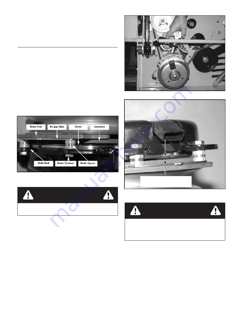
Check the air gap between rotor & armature with feeler gage.

If the gap is less than .070”, then follow the troubleshooting
procedure outlined in Warner Electric P1177 installation
troubleshooting guide available on Warner Electric’s web site-
www.Warnerelectric.com. If the air gap is over .070”, follow the
procedure outlined below. Figure 4-30 

1.

Loosen both brake mounting bolts 1/2 to 1 full turn as

shown in Figure 4-31. 

2.

Using needle nose pliers, or by hand, take hold of the tab
and remove shim (do not discard shim until proper clutch
function has been confirmed). Figure 4-32

3.

Using a pneumatic line, blow out any debris from under
the brake pole and around the aluminum spacers. Figure
4-29

4.

Re-torque each bolt (M6 X 1) to 120 in.-lbs.

5.

Using a .015” thick feeler gage, verify that a gap is
present between the rotor and armature face on both ends
of the brake pole as shown. Figure 4-33 and Figure 4-34   

a.

If the gap is less than .015” the clutch must be

Figure 4-28

WARNING

Always wear adequate eye protection when servicing the
mower.

Figure 4-29

Figure 4-30

WARNING

Do not remove brake pole from field shell/armature. The
brake pole tracks match with the clutch brake and need to
continue to match after shim is removed to ensure proper
brake torque. Figure 4-28

Be certain that the gap between the 

rotor and armature face is greater 

than .070” prior to shim removal.

Summary of Contents for Super Z HD

Page 1: ...117592 REV C Super Z HD General Service Manual 200 South Ridge Road Hesston Kansas 67062...

Page 2: ...contains chemicals known to the state of California to cause cancer birth defects or other reproductive harm NOTICE OF REQUIREMENT OF SPARK ARRESTER MUFFLER This equipment may create sparks that can...

Page 3: ...ment 4 4 Belts 4 5 Hydraulic Pump Belt Adjustment 4 5 Hydraulic system 4 6 Test Procedure for DDC20 Pump 4 7 New or Rebuilt DDC20 Pump Startup Procedure 4 8 Warner Clutch Re gap Adjustment Procedures...

Page 4: ...oning 6 8 Electrical 7 1 Electrical Schematic Kawasaki 7 1 Electrical Schematic Kawasaki 7 2 Electrical Schematic Kawasaki DFI 7 3 Electrical Schematic Briggs Stratton 7 4 Maintenance 8 1 Maintenance...

Page 5: ...grease oil and dirt especially in the engine compartment and under the seat platform areas minute dust particles are abrasive to close tolerance engine and hydraulic assemblies Daily inspect mower for...

Page 6: ...REV C 1 2 117592...

Page 7: ...ts or plastic truck bed liners Always place fuel containers on the ground away from your vehicle before filling When practical remove gas or diesel fuel powered equipment from the truck or trailer and...

Page 8: ...der the deck make certain engine cannot be accidentally started Shut engine off remove ignition switch key and disconnect negative bat tery cable for maximum safety Except when changing or checking be...

Page 9: ...te may overflow and damage paint wiring or structure When cleaning the battery use soap and water Be careful not to get soap and water into the bat tery Clean the battery terminals with a solution of...

Page 10: ...REV C 2 4 117592...

Page 11: ...l this fastener SIZE FT LBS N M SIZE FT LBS N M 10 32 4 IN LBS 3 6 M3 12 IN LBS 1 3 250 98 4 IN LBS 11 1 M4 26 4 IN LBS 3 312 204 IN LBS 23 M5 54 IN LBS 6 1 375 30 40 M6 92 4 IN LBS 10 4 438 48 65 M8...

Page 12: ...REV C 3 2 117592...

Page 13: ...ble for this mower On one seat you will disconnect the mower harness directly from the set switch as shown in Figure 4 1 On the other seat you will disconnect the wire harness from the two connectors...

Page 14: ...make the first adjustment the mower engine must not be running 2 Check to make sure the steering control levers are against the stops before the pumps are bottomed out internally 3 To do this gently a...

Page 15: ...ers in the park brake position disengage deck clutch remove ignition switch key and disconnect negative battery cable before doing any adjustments 2 Place the steering control lever in the neutral pos...

Page 16: ...half to one revolution Figure 4 12 6 Try and rotate the tire by hand The tire should rotate Remember hydraulic oil resistance will prevent the tire from rotating freely even with the bypass valves op...

Page 17: ...run against the bottom of the groove Replace the pulley when this is the case otherwise the belt will lose power and slip excessively Never pry a belt to get it on a pulley as this will cut or damage...

Page 18: ...he threads are right hand Hydraulic oil heat exchanger The Super Z HD is equipped with a hydraulic oil heat exchanger The heat exchanger coils must be kept clean to insure that the hydraulic oil is op...

Page 19: ...il supply lines from the motor and loosen supply lines at the pump One wheel motor fitting may need to be removed to assist with test line installation Cap the wheel motor ports or fittings 6 Test pro...

Page 20: ...seat switch This must be completed so that the safety circuit is functioning properly Figure 4 1 2 Remove Hustler Pressure Test Gauge Kit 3 After all repairs are completed check to make sure all tool...

Page 21: ...rs in the neutral position 9 Set engine throttle to the half throttle position 10 Start engine Run at idle for 30 seconds 11 Stroke steering control lever to the forward position NOTE If wheel motor d...

Page 22: ...27 14 Check to make sure all tools or obstructions are removed Figure 4 25 Prefill pump here Right side pump Prefill pump here Left side pump WARNING Do not operate the mower without plugging the mowe...

Page 23: ...an 070 then follow the troubleshooting procedure outlined in Warner Electric P1177 installation troubleshooting guide available on Warner Electric s web site www Warnerelectric com If the air gap is o...

Page 24: ...bleshooting guide available on Warner Electric s web site www Warnerelectric com and consult owner s manual Tires It is important for level mowing that the tires have the same amount of air pressure T...

Page 25: ...minutes for engine oil to adequately drain 4 After oil is drained close the valve by twisting it clockwise 5 Clean up any spilled oil IMPORTANT All oil drips or spills must be cleaned off of the exha...

Page 26: ...any manner because the condition of the filter after servicing is completely out of the filter manufacturer s control Therefore on a dust ingested engine failure there will be no warranty considerati...

Page 27: ...tings There are two rubber hoses that are connected to the fuel tanks One is the fuel hose that is part of the fuel system The other is the vapor line that is part of the fuel evaporative system The f...

Page 28: ...REV C 5 4 117592 Figure 5 9 Fuel evaporation system filter Vapor line Fuel tank Fuel tank Carbon canister Carbon canister...

Page 29: ...le 922222 no extension 922222 EX 922222 CE 922222 US Kawasaki FX850 FX1000 ENGINE SPEED MODEL NO ENDING WITH HIGH IDLE MODEL NO WITHOUT EXTENSION 3600 RPM MODEL NO WITH EX EXTENSION 3600 RPM MODEL NO...

Page 30: ...REV C 5 6 117592...

Page 31: ...against the stop handle Rear Discharge Decks all Place the height stop in the 3 25 82 6mm hole with the plate side of the height adjusting stop against the stop handle 5 Clamp the height adjusting sto...

Page 32: ...ake sure that there is still slack in the chain If not loosen the two nuts on the block holding the threaded rod until there is slack in the deck lift chain 21 Tighten the appropriate nut until the ch...

Page 33: ...eplace any distorted blade Do not re use spindle bolts which have stripped worn or undercut threads Torque bolts on spindles to 118 foot pounds 160 0 N m when reinstalling blades Properly compressed c...

Page 34: ...means of a tension idler and spring The spring tension should be such that the belt does not slip under normal operating load conditions assuming the belt is not excessively worn or damaged As the bel...

Page 35: ...117592 6 5 REV C Figure 6 13 Figure 6 14 Spring chain Spring chain anchor point Idler spring 60 Rear Discharge Deck Spring chain Spring chain anchor point Idler spring 72 Rear Discharge Deck...

Page 36: ...he different decks shown 1 Spring length after tensioning new belt Measured from outside of hook to outside of hook with deck set at 3 8 2 6mm cut height 2 Route belt as shown 60 66 72 Side Discharge...

Page 37: ...117592 6 7 REV C 60 Rear Discharge Deck Belt Routing Tensioning Figure 6 16 9 3 10 3 23 6 26 2cm 9 3 10 3 236 262mm...

Page 38: ...REV C 6 8 117592 72 Rear Discharge Deck Belt Routing Tensioning Figure 6 17 9 3 10 3 236 262mm 9 3 10 3 236 262mm...

Page 39: ...12122104 NOTE If replacing this harness with the updated version the six pin connector pigtail that is attached to the engine will need to be removed The updated version has individual connections fo...

Page 40: ...REV C 7 2 117592 Electrical Schematic Kawasaki Mowers with serial number 12122104 and later...

Page 41: ...117592 7 3 REV C Electrical Schematic Kawasaki DFI...

Page 42: ...REV C 7 4 117592 Electrical Schematic Briggs Stratton...

Page 43: ...ed parts Prior to each use Visually inspect tires Prior to each use Check oil level engine 1 Prior to each use or every 4 hours Clean oil heat exchanger 8 Prior to each use or every 4 hours Clean air...

Page 44: ...ation and then after every 500 hours of operation or yearly whichever comes first REFERENCES A Refer to engine owner s manual for engine service information NOTE After completing maintenance cycle 500...

Page 45: ...Engine Oil Filter 11 Deck Height Pivot Zerks 4 12 Park Brake Switch 13 Drive Tires 14 Pump Idler Zerk 1 15 Pump Belt 16 Deck Pusher Arm Zerks 2 17 Deck Belt 18 Spindle Housing Zerk 3 19 Blades 20 Fuel...

Page 46: ...Maintenance Service Performed Dealer Hour Meter Reading Date Maintenance Service Performed Dealer Hour Meter Reading Date Maintenance Service Performed Dealer Hour Meter Reading Date Maintenance Serv...

Page 47: ...broken Install a new traction drive belt Air in system Check filter and fittings For additional causes See engine manual Low engine oil pressure Low oil level Add oil Oil diluted or too light Change o...

Page 48: ...the Deck leveling and height adjustment section of the General Service Manual An anti scalp wheel is not set correctly Adjust the height of the anti scalp wheel The underside of the deck is dirty Clea...

Page 49: ...ance precautions 2 2 Hydraulic pump belt adjustment 4 5 Hydraulic system 4 6 Maintenance introduction 1 1 Maintenance precautions 2 2 Maintenance schedule 8 1 Mower blade maintenance 6 3 Mower blade r...

Page 50: ...INDEX PAGE PAGE REV C 1 2 117592...

Reviews: