background image

10

11

CONSUMER


ASSEMBLY / PRE-OPERATION

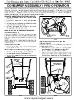
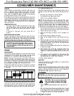
INSTALL CHUTE DEFLECTOR REMOTE CONTROL
(See Figs. 9 and 10)

1.    Install remote cable bracket to discharge chute with

5/16-18 carriage bolt, flat washer and 5/16-18 locknut 

as shown.  Tighten securely.

2.    Install  remote  cable  eyelet  to  chute  deflector  with

1/4-20  shoulder  bolt,  nylon  washer  and

1/4-20 locknut as shown.  Tighten securely.

3.    Install spring hooks between hex nuts on chute rotater 

head and into hole in chute deflector as shown.

INSTALL WEIGHT BAG (See Fig. 11)

Though seldom required, the weight bag will reduce the 

tendency of the auger housing to ride up on hard, icy drifts.  

Should conditions require it, install as follows:
1.    Shut off engine and wait for all moving parts to stop.
2.    Fill weight bag with desired amount of sand.
3.    Place weight bag on top of auger housing with mount-

ing clamp at front edge of auger housing as shown.

IMPORTANT: 

Mount the weight bag in a location which 

does  not  cover  the  warning  decals  on  top  of  the  auger 

housing.

CHECK TIRE PRESSURE

The tires on your snow thrower were overinflated at the fac-

tory for shipping purposes.  Correct and equal tire pressure 

is important for best snow throwing performance.
•      Reduce tire pressure to 14-17 PSI.

WEIGHT 

BAG

5/16-18 x 1-1/2 

CAPSCREWS

BAR

AUGER HOUSING

MOUNTING 

CLAMP

FIG. 11

CHUTE DEFLECTOR 

CONTROL LEVER

FIG. 10

HOOK BETWEEN 

HEX NUTS

ON CHUTE RO-

TATER HEAD

SPRING

CHUTE DE-

FLECTOR

5/16-18 

CARRIAGE 

BOLT

5/16-18 LOCK-

NUT

REMOTE 

CABLE 

BRACKET

1/4-20 

LOCK-

NUT

FLAT 

WASHER

CABLE EYE-

LET

NYLON 

WASHER

1/4-20 

SHOULDER 

BOLT

FIG. 9

For Husqvarna Parts Call 606-678-9623 or 606-561-4983

www.mymowerparts.com

Summary of Contents for OHV

Page 1: ...H O M E P R O D U C T S SNOWTHROWER SERVICE MANUAL For Husqvarna Parts Call 606 678 9623 or 606 561 4983 www mymowerparts com ...

Page 2: ...ng parts When working on a snowthrower or any lawn and garden equipment develop and follow safe working practices Wear appropriate close fitting clothing Use safety equipment i e gloves safety glasses or hearing protection Always remove the spark plug wire when working on a machine Use the proper tools and use torque wrench on fasteners indicated in this manual Use power tools only to loosen threa...

Page 3: ...ions 6 Section 3 Assembly 7 Section 4 Maintenance Storage and Operation 17 Section 5 Troubleshooting Chart 22 Section 6 Adjustments 23 Section 7 Systems and Repair Procedures 27 50 Service Notes 51 For Husqvarna Parts Call 606 678 9623 or 606 561 4983 www mymowerparts com ...

Page 4: ...AZARD Never fill containers inside a vehicle or on a truck or trailer bed with a plastic liner Always place containers on the ground away from your vehicle before filling When practical remove gas powered equipment from the truck or trailer and refuel it on the ground If this is not possible then refuel such equipment on a trailer with a portable container rather than from a gasoline dispenser noz...

Page 5: ...ate the snow thrower near glass enclo sures automobiles window wells drop offs and the like without proper adjustment of the snow discharge angle Keep children and pets away Do not overload the machine capacity by attempting to clear snow at too fast a rate Never operate the machine at high transport speeds on slippery surfaces Look behind and use care when backing up Never direct discharge at bys...

Page 6: ...Part Number 179092 Cog V Belt Use OEM part only WHEELS 13 or 16 TIRE PRESSURE 14 to 17 PSI in operation SNOWTHROWER AUGER SYSTEM 24 27 or 30 Widths AUGER BELT Part Number 183533 Use OEM part only GEARBOX Worm with Gear No Maintenance Required SCRAPER BAR Reversible Replaceable SKID PLATES Adjustable Replaceable FASTENERS THAT MUST BE TORQUED BOLTS HOLDING ENGINE TO CHASSIS 25 to 30 Ft Lb LOWER HAN...

Page 7: ...7 PARTS PACKED SEPARATELY IN CARTON SECTION 3 CONSUMER ASSEMBLY For Husqvarna Parts Call 606 678 9623 or 606 561 4983 www mymowerparts com ...

Page 8: ...and parts boxes from carton 2 Cut down all four corners of carton and lay panels flat 3 Remove all packing materials except plastic tie holding speed control rod to lower handle 4 Remove snow thrower from carton and check carton thoroughly for additional loose parts HOW TO SET UP YOUR SNOW THROWER TOOL BOX See Fig 12 A toolbox is provided on your snow thrower The toolbox is located on top of the b...

Page 9: ...with discharge opening toward front of snow thrower 2 Position chute rotater head over chute bracket If nec essary rotate chute assembly to align square and pin on underside of chute rotater head with holes in chute bracket 3 With chute rotater head and chute bracket aligned position chute rotater head on pin and threaded stud of mounting bracket 4 Install 3 8 washer and locknut on threaded stud a...

Page 10: ... parts to stop 2 Fill weight bag with desired amount of sand 3 Place weight bag on top of auger housing with mount ing clamp at front edge of auger housing as shown IMPORTANT Mount the weight bag in a location which does not cover the warning decals on top of the auger housing CHECK TIRE PRESSURE The tires on your snow thrower were overinflated at the fac tory for shipping purposes Correct and equ...

Page 11: ...rations with your snow thrower to familiarize yourself with the location of various controls and adjustments Save this manual for future reference These symbols may appear on your snow thrower or in literature supplied with the product Learn and understand their meaning For Husqvarna Parts Call 606 678 9623 or 606 561 4983 www mymowerparts com ...

Page 12: ...mer pumps additional fuel from the carburetor to the cylinder for use when starting a cold engine Choke Control used for starting a cold engine Throttle engine control used to select either FAST or SLOW engine speed and to STOP the engine MEETS A N S I SAFETY REQUIREMENTS Our snow throwers conform to the standards of the American National Standards Institute TRACTION DRIVE CON TROL LEVER DISCHARGE...

Page 13: ...e snow thrower with the engine at full throttle Full throttle offers the best snow thrower performance The operation of any snow thrower can result in foreign objects thrown into the eyes which can result in severe eye damage Always wear safety glasses or eye shields while operating your snow thrower or performing any adjustments or repairs We recommend standard safety glasses or a wide vision saf...

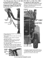
Page 14: ... triggers are located on the underside of each handle When a trigger is squeezed it disengages the drive wheel on that side of snow thrower and allows it to turn in that direction To turn left squeeze left side trigger To turn right squeeze right side trigger TO ADJUST SKID PLATES See Fig 20 NOTE The wrench provided in your parts bag may be used to adjust the skid plates Skid plates are located on...

Page 15: ... may occur 1 Shut off engine and wait for all moving parts to stop 2 Adjust skid plates by loosening the rear 1 2 hex nut only thenmovingskidplatetodesiredposition Besure both plates are adjusted evenly Tighten securely CONSUMER OPERATION TO START ENGINE Be sure fuel shut off valve is in the OPEN position Your snow thrower engine is equipped with both a 120 Volt A C electric starter and a recoil s...

Page 16: ... the engine or starter 4 Disconnect the power cord from the receptacle first then from the engine CONSUMER OPERATION RECOIL STARTER 1 Whiletheengineisrunning pulltherecoilstarterhandle with rapid full arm strokes three or four times NOTE The unusual sound made while pulling the recoil starter handle will not harm the engine or starter IF RECOIL STARTER HAS FROZEN If the recoil starter has frozen a...

Page 17: ... this unit Failure to do so can cause the unit to malfunction and pose a risk of injury to the operator BEFORE EACH USE 1 Check engine oil level 2 Check for loose fasteners 3 Check controls to be sure they are functioning prop erly LUBRICATION Keep your snow thrower well lubricated See LUBRI CATION CHART SNOW THROWER Always observe the safety rules when performing any maintenance TIRES Maintain pr...

Page 18: ...th spark plug Keep finished surfaces wheels free of gasoline oil etc We do not recommend using a garden hose to clean your snow thrower unless the electrical system muffler and carburetor are covered to keep water out Water in engine can result in shortened engine life CONSUMER MAINTENANCE V BELTS Check V belts for deterioration and wear after every 50 hours of operation and replace if necessary T...

Page 19: ... come in contact with spark plug 3 Align hole in auger hub with hole in auger shaft and install a new 1 4 20 x 2 shoulder shear bolt Install 1 4 20 lock nut and tighten securely CAUTION Do not substitute Use only original equipment shear bolts as supplied with your snow thrower 4 Connect spark plug wire to spark plug IMPELLER SHEAR BOLTS The impeller is secured to the impeller shaft with two 2 cap...

Page 20: ...rom the frame assembly it is important that an assistantstandintheoperatingposition andholdthesnowthrowerhandles Se rious personal injury and or damage to theunitcouldoccurifthesnowthrower should fall during the belt changing process HINT Insert a 3 8 drive ratchet in the ON position into the square hole in idler arm and rotate ratchet clockwise to relieve tension 8 With tension relieved on idler ...

Page 21: ... drain the gas tank and carburetor if using fuel stabilizer ENGINE OIL Drain oil with engine warm and replace with clean en gine oil See ENGINE in the Maintenance section of this manual CYLINDER 1 Remove spark plug 2 Pour one ounce 29 ml of oil through spark plug hole into cylinder 3 Pull recoil starter handle slowly a few times to distribute oil 4 Replace with new spark plug OTHER Do not store ga...

Page 22: ... runs roughly 2 Blockage in fuel line 2 Clean fuel line 3 Stale fuel 3 Drain tank and refill with fresh clean fuel 4 Water in fuel 4 Drain fuel tank and carburetor refill tank with fresh gasoline 5 Carburetor is in need of 5 Contact a qualified service center adjustment or overhaul Excessive 1 Loose parts or damaged 1 Tighten all fasteners Replace damaged parts vibration augers or impeller If vibr...

Page 23: ...tion for wheels on Power Steering Drive Snowthrower 6 01 Belt Guide Remove spark plug wire from plug Engage auger lever and adjust clearance be tween belt and belt guide to 1 16 to 1 8 To Push the snowthrower easily the Klik Pin should be through the outer axle hole with the wheel hub to the inside For the wheel to drive the Klik Pin should be positioned through both the wheel hub and inner axle h...

Page 24: ...Rod p 35 key 36 When a new rubber ring is installed this nut is adjusted so that two threads are showing past the nut When the ring is worn it can be adjusted with up to 1 2 of rod past the nut This increases the force of the drive plate on the rubber ring to stop slipping The nut should never be turned so that more than 1 2 extends beyond the nut See Section 7 43 NOTE If the Plates supporting the...

Page 25: ...sconnect control rod from control lever Turn the rod counter clockwise to lengthen clockwise to shorten Reconnect the control rod to the control lever The linkage should be slightly loose If not readjust then tighten jam nut Test auger disengagement Stopping time must be 5 seconds or less If stopping is more than 5 seconds readjust rod for more slack Remove belt cover and check to see if idler arm...

Page 26: ... all parts with needed thrust washers Use antiseize compound on splined parts during reassembly Refer to page 33 for exploded parts view Reinstall Thrust Washer p 37 key 27 Axle Lobe 26 Wheel Lobe 23 and Retaining Ring key 33 Pull axle shaft outward to maximize tolerances Remove wheel and power steering parts on side with slipping power steering Section 7 22 Place Snowthrower with Auger end down F...

Page 27: ... Traction Drive Belts 7 35 Replace Traction Drive Pulley 7 36 Idler Spring Locations 7 37 Remove And Replace Engine 7 41 Exploded view of Friction Disc Friction Plate and Gears 7 42 Procedure to Remove Bottom Pan 7 43 Replace Friction Disc or Friction Disc Shaft 7 44 Replace Rubber Wheel Ring or Hex Shaft 7 45 Replace Drive Plate Assembly Lubrication INSTRUCTION 7 46 Disassemble Drive Plate Drive ...

Page 28: ...28 SNOW THROWER SECTION 7 10 HANDLES For Husqvarna Parts Call 606 678 9623 or 606 561 4983 www mymowerparts com ...

Page 29: ...l remain engaged as long as the traction lever is also held down This is to allow the operator to adjust the discharge chute direction without stopping If problems occur with interlock check the spring and look for wear on the bracket You will see this on the right with the console panel removed Use two fingers to push up on Headlight Bezel to release bottom tabs and remove Headlight To remove har...

Page 30: ...30 SNOW THROWER SECTION 7 14 CONTROL PANEL DISCHARGE CHUTE For Husqvarna Parts Call 606 678 9623 or 606 561 4983 www mymowerparts com ...

Page 31: ...s to install new cable Install new plastic ties to hold cables 2 Remove both 5 16 screws holding rotator control to handle assembly 4 Remove both 5 16 screws that secure cable assembly to the handle assembly 5 Cut the cable ties that secure the cable to the snowthrower paying attention to the routing of the cable and the location of ties 6 Reverse process to install the cable and new plastic ties ...

Page 32: ...inkage and perform adjustment in Section 6 24 3 Remove retainer spring from both ends of linkage 9 Remove 5 16 screw that secures trigger to handle 10 Reverse process to install cable 7 Remove spring and pin holding bellcrank 8 Unhook cable from bellcrank Remove 5 16 screw that secures trigger to handle Remove cable 5 Remove hardware that secures the power steering cover 6 Cut wire ties that secur...

Page 33: ...33 SNOW THROWER SECTION 7 21 POWER STEERING AND WHEELS For Husqvarna Parts Call 606 678 9623 or 606 561 4983 www mymowerparts com ...

Page 34: ...ring uses Klik Pin in one position only 7 23 If Power Steering Slips 2 Push wheel hub in towards the body of the blower 1 To freewheel for models without power steering remove klik pin from axle Go to 6 31for procedure to add shim washer if power steering slips on one side SPRING CABLE PIN LINK BELLCRANK RETAINER SPRING SPRING For Husqvarna Parts Call 606 678 9623 or 606 561 4983 www mymowerparts ...

Page 35: ...35 SNOW THROWER SECTION 7 31 CHASSIS ENGINE PULLEYS For Husqvarna Parts Call 606 678 9623 or 606 561 4983 www mymowerparts com ...

Page 36: ...rom the powerhead assembly 7 Place new belt on auger pulley 8 Lift auger housing into position and ensure that slotted bracket on auger housing are placed onto the rod at base of powerhead 10 Reinstall bolts to secure auger housing to the powerhead 11 Reinstall the belt cover and the chute assembly See Section 7 51 9 Route auger belt around pulleys checking that the belt does not catch on idler br...

Page 37: ... attach auger housing to powerhead see section 7 61 or section 7 32 7 36 Idler Spring locations 7 33 Belt Guide Dimension AUGER BELT SPRING TRACTION BELT SPRING 7 35 Replace Traction Drive Pulley 1 Separate powerhead assembly from auger housing assembly see section 7 61 2 Remove Traction Drive Belt Section 7 33 from engine pulley 3 Use traction drive belt to prevent drive pulley from turning remov...

Page 38: ... support will help to position engine while starting self tapping screws Torque screws holding engine to chassis at 25 30 Ft Lbs 13 Reinstall Drive Plate Assembly Section 7 45 14 Place wheels back on axles so the blower can be tipped back into operating position Reinstall engine pulleys idler bracket with idler pulley belt guide attach idler spring and belts Adjust Belt Guide as shown in Section 6...

Page 39: ...39 SNOW THROWER SECTION 7 41 DRIVE For Husqvarna Parts Call 606 678 9623 or 606 561 4983 www mymowerparts com ...

Page 40: ...move the four Hex Head Screws that hold the bottom pan to the frame 8 Reverse to reassemble 5 Pull bearing hex shaft assembly out from left side 6 Remove Assembly with Rubber Wheel Ring from shifter fork and support Plates 7 Replace Rubber Wheel Ring and torque bolts to 14 18 Ft Lbs 8 Reverse process to install Lubricate hex shaft with metallic anti seize before re installing Check to see that tru...

Page 41: ...ve control bellcrank 4 Remove the 4 screws 2 each side from the frame that hold the mounting drive plate in place The zinc plated screws on left side are slightly longer 5 Remove belt from pulley 6 Slide Drive Plate Assembly out NOTE Whenever this assembly is removed it is strongly suggested to lubricate the Hex Shaft with anti seize compound See Section 7 46 for instructions 7 Place belt on pulle...

Page 42: ...on If this assembly is removed we recommend the hex shaft is lubricated with anti seize compound 1 Unhook Spring from Clutch Rod key 11 2 Remove Hairpin Retainer key 22 from the Shift Plate Lever 3 Remove Pivot Pin and separate Drive Plate key 26 from hex shaft 4 Slide the axle out the right side and replace damaged parts 5 Reverse process to reassemble Make sure the square key roll pin and thrust...

Page 43: ...ove Deflector Chute Section 7 51 Chute Removal 3 Remove both 3 8 screws that secure belt cover Remove belt cover 4 Place a chair or saw horse behind handle assembly for support after auger section is split 5 Remove both 9 16 hex bolts that hold the powerhead and auger housing together To Reinstall 7 Place belt on auger pulley and use to lift auger assembly into position so that slotted bracket on ...

Page 44: ...44 SNOW THROWER SECTION 7 62 AUGER HOUSING IMPELLER ASSEMBLY For Husqvarna Parts Call 606 678 9623 or 606 561 4983 www mymowerparts com ...

Page 45: ...lley from the impeller shaft It may be necessary to use a gear puller for this If so it may help to put a small socket between the gear puller screw and the shaft 4 Using emery cloth clean and smooth the surface of the shaft 5 Remove the right and left side bolts 3 8 that hold the auger bearings in place IMPELLER SHEAR BOLTS 49 AUGER SHEAR BOLTS 28 6 Holding the Auger pull up to remove the impelle...

Page 46: ...ll as the auger width 4 Reinstall screws to side of housing to secure the auger bearings 5 Turn Auger assembly over put antiseize compound on impeller shaft before installing pulley Torque at 15 20 Ft Lbs 6 Reinstall belt and reattach auger assembly to powerhead Section 7 61 or 7 31 1 Tip snowthrower so that Auger is down and handles are up 2 Remove the nuts and carriage bolts holding the scraper ...

Page 47: ...47 TECUMSEH 4 CYCLE OHV ENGINE For Husqvarna Parts Call 606 678 9623 or 606 561 4983 www mymowerparts com ...

Page 48: ...ludes Key Numbers 71 75 and 80 thru 84 71 Crankshaft Bushing 72 Oil Drain Plug 75 Oil Seal KEY PART NO NO DESCRIPTION 80 Governor Shaft 81 Washer 82 Governor Gear Assembly Includes Key Number 81 83 Governor Spool 84 Retaining Ring 86 Screw 1 4 20 x 1 3 16 87 Screw 1 4 20 x 1 11 16 89 Flywheel Key 90 Flywheel with Ring Gear 92 Lock Washer 93 Flywheel Nut 100 Solid State Ignition Includes Key Number...

Page 49: ...cludes Key Numbers 292 and 301 301 Fuel Cap 302 Fuel Tank Extension 302A Screw 10 32 x 1 2 KEY PART NO NO DESCRIPTION 305 Oil Fill Tube 307 O Ring 308 Fill Tube Clip 310 Dipstick 314 Screw 1 4 20 x 3 4 315 Alternator Coil 18 Watt Includes Key Numbers 322 and 323 322 Connector Body 323 Terminal 328 Ignition Keys 329 Terminal 335 Carburetor Cover Front 335A Carburetor Cover 336 Screw T 30 1 4 20 x 1...

Page 50: ...ket 36 Main Nozzle Tube 37 O Ring Main Nozzle Tube 40 High Speed Bowl Nut 44 Bowl Nut Washer 47 Welch Plug Idle Mixture Well 48 Welch Plug Atmospheric Vent 60 Repair Kit Incl Items Marked KEY PART NO NO DESCRIPTION Electric Starter 110 Volt 1 Dust Cover 2 Retainer Ring 3 Spring Retainer 4 Anti drift Spring 5A Gear Nut Incl 2 6 Drive End Cap Assembly Incl 7 7 O Ring 8 Armature 9 Housing Assembly 10...

Page 51: ...51 SERVICE NOTES For Husqvarna Parts Call 606 678 9623 or 606 561 4983 www mymowerparts com ...

Page 52: ...Part Number 184962 _ printed for MY 2003 For Husqvarna Parts Call 606 678 9623 or 606 561 4983 www mymowerparts com ...

Reviews: