To replace the blade and fan
WARNING: Use heavy duty gloves. The
blade is very sharp and cuts can easily
occur.
1. Prepare the product for maintenance work, see
Before you do maintenance work on page 10
.
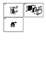
2. Hold the fan tightly and turn the blade bolt (A)
counterclockwise to remove it.(Fig. 32 )
3. Remove the blade (B), cutting height spacers (C)
and the fan (D).
4. Examine the blade bolt and the fan for damages.
5. Put the fan back in its initial position. If you add
cutting height spacers, make sure that the pins are
put in the holes on the fan.
6. Attach the new blade. Make sure that the pins on the
fan (E) are put in the holes (F) on the blade.
7. When you attach the new blade, point the angled
ends of the blade in the direction of the ground.
8. Put the blade bolt through the center hole of the
blade (G) and tighten clockwise by hand.
9. Hold the fan tightly and tighten the blade bolt with a
wrench.
10. Pull the blade around by hand and make sure that it
turns freely.
11. Start the product to do a test of the blade. If the
blade is not correctly attached, there is vibration in
the product or the cutting result is unsatisfactory.
To set the cutting height
Add cutting height spacers to decrease the cutting
height. Remove the cutting height spacers to increase
the cutting height.
Note: Do not use more than 2 cutting height spacers.
1. Prepare the product for maintenance work, see
Before you do maintenance work on page 10
.
2. Remove the blade bolt and the blade, see
To
replace the blade and fan on page 12
.
3. Put 1 or 2 cutting height spacers (A) between the fan
and the blade. Put the holes on the first cutting
height spacer on the pins on the fan (B). Put the pins
on the second cutting height spacer in the holes on
the first cutting height spacer.(Fig. 33 )
4. Put the blade on the cutting height spacer. Make
sure that the pins on the cutting heigt spacer are put
in the holes (C) on the blade.
5. Attach the blade and the blade bolt, see
To replace
the blade and fan on page 12
.
To fill and change the engine oil
• For information how to fill and change the engine oil,
refer to the operator's manual for the engine.
To clean the air filter
CAUTION: Do not operate the engine
without an air filter attached or with a dirty air
filter. This decreases the efficiency and can
cause damage to the engine.
1. Press the latch tabs (A), remove the air filter cover
(B) and remove the air filter (C).(Fig. 34 )
2. Hit the air filter against a flat surface to make the
particles fall off. You can also blow compressed air
through the air filter from the clean side of the air
filter.
CAUTION: Do not use a brush to
remove dirt as this pushes the dirt into
the air filter.
3. Clean the air filter holder (D) and the air filter cover
with a moist cloth.
CAUTION: Do not let dirt enter the air
duct that leads to the carburetor (E).
4. Put the air filter back in its initial position. Make sure
that the air filter fully seals against the air filter
holder.
5. Put the air filter cover back with the bottom tabs first.
To examine the spark plug
CAUTION: Always use the recommended
spark plug type. Incorrect spark plug type
can cause damage to the product.
• Examine the spark plug if the engine is low on
power, is not easy to start or does not operate
correctly at idle speed.
• To decrease the risk of unwanted material on the
spark plug electrodes, obey these instructions:
a) Make sure that the idle speed is correctly
adjusted.
b) Make sure that the fuel mixture is correct.
c) Make sure that the air filter is clean.
• If the spark plug is dirty, clean it and make sure that
the electrode gap is correct, see
Technical data on
page 13
.(Fig. 35 )
• Replace the spark plug if it is necessary.
To examine the fuel system
• Examine the fuel tank cap and the seal for the fuel
tank cap to make sure that there are no damages.
• Examine the fuel hose to make sure that there are
no leaks. If the fuel hose is damaged, let a service
agent replace it.
12
504 - 003 - 26.01.2018
Summary of Contents for Flymo XL500
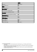
Page 2: ...13 2 3 4 5 14 15 7 9 6 1 12 11 10 8 1 2 3 4 5 6 7 8 9 10 11 12 13 14 15 D A B 90 C 16 ...
Page 3: ...A B 17 18 19 D A B 90 C 20 A 21 A B C D E 22 A B 23 A B C 24 ...
Page 4: ...25 26 27 28 29 30 A 31 A B G F E D C 32 ...
Page 5: ...B A C 33 B C D E A 34 35 ...
Page 36: ...XL500 Klinge Artikelnummer 5119004 10 36 504 003 26 01 2018 ...
Page 123: ...504 003 26 01 2018 123 ...


