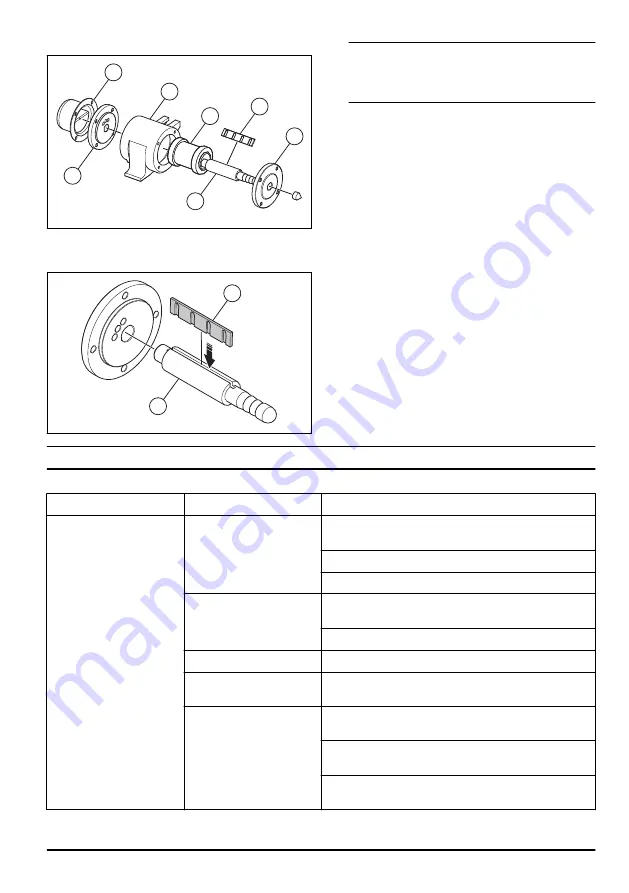
2. Replace the lamella (A) on the shaft (B).
C
E
D
F
A
G
B
3. Adjust the thickness of the lamella with 800 grit
abrasive paper for a tight fit in the groove of the
shaft.
A
B
Note: Keep the lamella 1 night in oil until assembly to
prevent changes in thickness because of moist
conditions. Only adjust the thickness of the flat
surface of the lamella.
4. Put a position tool into the first exhaust hole on the
right side of the rear flange (C).
5. Put the shaft into the rear flange. Make sure that the
lamella is level with the position tool.
6. Remove the position tool.
7. Put the flange assembly into the housing (D) with the
exhaust holes at the top side and the lamella on the
right side.
8. Put the rear cover (E) on the rear flange. The
exhaust holes must be opposite to the holes on the
rear flange.
9. Assemble the rotor (F).
10. Assemble the front flange (G). The inner side holes
must be opposite to the holes on the rear flange.
11. Assemble the 8 screws for the rear flange and front
flange. Tighten the screws to the correct torque 21.6
Nm.
Troubleshooting
Problem
Cause
Solution
The product does not start. There is no air pressure.
Make sure that the air compressor is on and that the
product is correctly connected to the air hose.
Make sure that the air hose is not blocked or twisted.
Examine the air flow and the air pressure.
There is no air flow.
Make sure that the air compressor is on and that the
product is correctly connected to the air hose.
Make sure that the air hose is not blocked or twisted.
The air exhaust is blocked. Remove the blockage. Clean the air exhaust.
The product does not oper-
ate correctly.
Make sure that there is no mechanical friction or block-
age in the product.
Examine the lamella. Make sure that the lamella is as-
sembled correctly and is not damaged.
Examine the product parts. Make sure they are not dam-
aged from corrosion.
Make sure that the rotor is in the correct position. Refer
to
To operate the product on page 6
.
1579 - 001 - 18.12.2020
7


