background image

English - 28

Press 

BACK

 to exit the test.

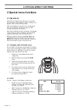
Charging station

This function is used to quickly check that there is 

a signal for A, F, N and the Guide wires. The test also 

shows whether the mower is receiving a charge from 

the charging station. 
Place the mower in the charging station and start the 

test.
Note! The robotic lawnmower must be synchronised 

with and placed in the charging station to be able to 

conduct the test. Use the 

New loop signal

 function 

in the 

Security

 menu to synchronise.

It is recommended to use 

Info - Battery

 and 

Info - Loop 

to carry out a more exact inspection of signal strength 

and charge current. 

2.6.5 Special settings

The 

Special settings 

sub-menu contains the settings 

that are only accessible for dealers.

Override loop detection

This function makes it possible to temporarily switch 

off a mower’s loop detection, i.e. to be able to run it 

without the charging station and boundary loop being 

installed. One such occasion can for instance be 

a demonstration of a robotic lawnmower at the home 

of a customer.
The function is reset automatically when the mower 

is turned off and on using the main switch. 

Demo mode

In demo mode the robotic lawnmower works without 

starting the blade disc. The mower alternates between 

4 minutes operation and a short charge. 
The Demo mode is ideal for use in installations such 

as in shops or exhibitions.
The function is reset automatically when the mower 

is turned off and on using the main switch. 

Installation settings lock

When the installation settings lock is activated, it is 

not possible to change any settings in the 

Installation


menu from the main menu. This function must be 

deactivated to carry out any changes to the installation 

settings. 

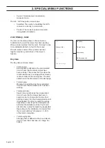
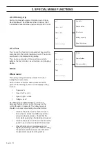
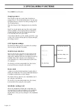
Info

History, total

History, trip

Test

Special settings

Override loop detection

Demo mode

Installation settings lock

Calibrate tilt sensor

2. SPECIAL MENU FUNCTIONS

Summary of Contents for Automower 320

Page 1: ...HUSQVARNA AUTOMOWER 320 330X TECHNICAL MANUAL ...

Page 2: ......

Page 3: ...gin 42 4 2 Connection to the robotic lawnmower 43 4 3 Use 45 5 Repair instructions 52 5 1 Design and function 53 5 2 Disassembling and assembling the robotic lawnmower 56 5 3 Disassembling the charging station 61 5 4 Assembling the charging station 61 5 5 Replacing the charging strips 62 5 6 Replacing the battery 62 5 7 Replacing the main circuit board 62 5 8 Replacing the MMI circuit board 64 5 9...

Page 4: ... robotic lawnmower be modified without the expressed permission of the manufacturer Unauthorized modifications and or components can result in serious disruptions and the risk of personal injuries Only use original spare parts Husqvarna AB has a policy of continuous product development and therefore reserves the right to modify the design appearance and function of products without prior notice Mo...

Page 5: ...king button not available with Automower 320 10 Charging station 11 Rating plate 12 Display 13 Keypad 14 Cutting system 15 Chassis box with electronics battery and motors 16 Handle 17 Main switch 18 Blade disc 19 Skid plate 20 Transformer 21 Loop wire for boundary loop and guide wire 22 Low voltage cable 23 Pegs 24 Connector for the loop wire 25 Screws for securing the charging station 26 Measurem...

Page 6: ...ce program repair instructions and troubleshooting To make it easier to follow the following structure is used Text written in italics is a text that is shown on the mower s display or in the menus in the Autocheck Experience service program Words that are written in bold represent one of the keys on the mower s keypad or a key in the Autocheck Experience service program Words written in UPPERCASE...

Page 7: ...area of 2 200 m2 43 kWh month for a working area of 3 200 m2 Mean charging time 50 70 minutes 50 70 minutes Mean cutting time 50 70 minutes 130 170 minutes Noise emissions Measured Noise Level 56 dB A 56 dB A Guaranteed noise level 58 dB A 58 dB A Mowing Cutting system Three pivoted cutting blades Three pivoted cutting blades Blade motor speed 2 300 rpm 2 300 rpm Power consumption during cutting 3...

Page 8: ... 00 of the MMI program 1 4 1 Ascertaining the program version 1 Set the main switch to position 1 2 When the start page is displayed Keep the 0 key pressed in for two seconds to go to Quick Check 3 Select Info and press OK 4 Select General and press OK 5 The main program s version is indicated on the line that starts MSW ver e g 3 08 00 The MMI program s version is indicated on the line that start...

Page 9: ...awnmower than on a conventional mower It is the principle of the cutting the grass instead of knocking it off that makes this difference The double edged blades together with the technology that rotates the blade disc in both directions increase the life of the blades In order to keep the blades sharp for as long as possible it is important to keep the lawn free from branches small stones and othe...

Page 10: ...hardly visible The robotic lawnmower always attempts to keep the blade disc at an even speed Different degrees of power are used for this depending on the length thickness of the grass The Automower compares the instantaneous power with an average power value from the latest hours of mowing This means that when the robotic lawnmower enters an area where the lawn is longer thicker than before the i...

Page 11: ...sage F signal Remote signal from the charging station which is generated by a loop in the charging station plate The F signal is used so that the mower knows that it is in the vicinity of the charging station There may be reasons to reduce the range of the charging station in rare cases It may be necessary if for instance the charging station is placed close to a bush or wall which prevents the ro...

Page 12: ... on the boundary loop being over 800 m in length or that the wire is damaged If the mower still works this is not a problem Solid red light fault in the circuit board in the charging station See 6 4 Troubleshooting the loop signal for suggestions on steps to take in case of errors 1 8 Boundary loop The strength of the signal in the boundary loop is constant in a loop that is up to approx 800 metre...

Page 13: ...Examples of magnetic objects are iron fences iron girders and reinforcement bars Grass areas laid on concrete roofs can therefore receive a weakened signal When the signal is reinforced or weakened it is normal that both low and high signal strengths are not always available along the entire boundary loop The loop signal s reception and amplification in the mower can also vary by 10 from one mower...

Page 14: ...of the guide signal also varies along the guide loop depending on the proximity to other parts of the guide loop and is affected by islands headlands passages and corners To reduce the risk of the mower losing contact with the wire in corners it is recommended to not lay the wire at 90 degree angles It is better to lay the wire in two 135 degree angles 1 10 Searching methods to find the charging s...

Page 15: ...mower will also start searching for the boundary loop If the mower then finds and follows the boundary loop it keeps going until it has found the charging station or crosses the guide wire If it crosses the guide wire the robotic lawnmower will follow it instead to the charging station When the mower follows the boundary loop or a guide wire it travels a distance into the F field before the F and ...

Page 16: ...pped with a Li Ion battery Compared with a NiMH for example Li Ion has very good properties even at high ambient temperatures The battery also has low self discharge i e it can remain unused for a longer period than for example NiMH without being damaged Counted in number of charging cycles the service life is also expected to be longer for Li Ion than NiMH Charging is primarily controlled by the ...

Page 17: ...ates left to right inclination The value from the tilt sensor is used among other things to compensate the operation of the wheel motors when mowing on slopes 1 14 3 Lift sensors The lift sensors are the sensors that sense if the mower is being raised off the ground This is done with the help of the mechanical design and magnets in each of the two front collision columns If the lift signal is indi...

Page 18: ...ber of the display modes below for instance Loop it may be necessary to make a note of the values when the mower is operating To do this the mower hatch must be open while it operates 1 Select one of the display modes shown in Quick Info 2 Start the mower by pressing the START button 3 Instead of closing the hatch as is normal press in the hatch locking devices with the hatch open 4 The mower will...

Page 19: ...tt 2 provides information on each battery Voltage The battery s current voltage level About 20 5 V indicates a fully charged battery and about 17 V indicates a flat battery Chargings The accumulated number of charges since date of manufacture or the counter was reset Charge level Shows the charge remaining in the battery When the battery is fully charged the charge is approximately 5 100 mAh 2 600...

Page 20: ...through the loop sensors in the mower The loop signals can only be interpreted if the value for Quality is 100 If the value is 99 or lower the loop system does not function correctly and thus none of the values displayed for the signals are correct The Info Sensors Status display mode shows Collision front and Collision rear One way of testing the collision sensor is to hold the mower chassis by t...

Page 21: ... and time when the message was set The By frequency display mode show for each message Position in the message list The faults are sorted according to frequency with the most frequent at the top Message title The number of times this fault has occurred since the latest fault message reset The History Messages Info messages display mode shows the last 50 messages that the mower has registered but d...

Page 22: ...th the same PIN code Contact the national service organisation and state the letter combination and serial number They can then identify the right PIN code Press BACK to exit the function 2 3 Tools menu In addition to the main menu selections which are described in the Operator s Manual there is a further one called Tools The Tools menu includes the possibility of testing a mower s components and ...

Page 23: ...e Schedule Fault messages By date By date Low Run spiral cutting Area 1 5 High Overview Medium Intensity GPS Custom Reset New loop signal Time Date Time format Flashes when fault Reset messages Duration of alarm Duration of time lock Change PIN code Spiral cutting Set date Luminosity Headlight Info messages By frequency By frequency Advanced Langu age Date format Reset security settings Calibrate ...

Page 24: ...y total History trip Test Special settings Loop Calibrate tilt sensor Mow times Sound Battery Battery Demo Search times Blade motor Display User interface Reset trip values Sensors Guide calibration Battery capacity Charging station Motors Installation settings lock GPS Only 330X Wheel motor 2 SPECIAL MENU FUNCTIONS ...

Page 25: ... sensors The menu can be used in connection with e g troubleshooting The General Battery Loop and Sensors functions show the same information as in the Quick Info menu above The Info Motors Wheel menu shows for the right and left wheel motors Speed The wheel motors speed in cm s Current Nominal power consumption measured in mA Power The actual power the wheel motors are currently being operated wi...

Page 26: ... is running without mowing is also included in the running time The time stated here is the time stated on the start page Total mowing Mowing time is defined as the accumulated time in hours that the blade motor has been working Total search time Search time is defined as the accumulated time in hours that the mower has been in search mode in other words the time from starting to search for the ch...

Page 27: ...tor has been in operation The list shown contains the times of the last 12 search occurrences measured in minutes Battery capacity This part menu contains information about the battery s capacity Checking the battery s capacity requires that the battery is completely flat For more information see 6 6 Battery test The four most recent battery tests are saved in Battery capacity The following is sho...

Page 28: ... cm s Speed right xx cm s Voltage xx x V Use Arrow up and Arrow down to increase or decrease the wheel force and in this way run the motors forward or backward The following points should be checked when testing the wheel motors Increase the power to 80 and block each drive wheel in at least ten different positions along the wheel revolution Check that the motor starts again when the blocking is r...

Page 29: ...nds and feet at a safe distance WARNING The following values are shown on the display Speed The speed is normally 2 300 rpm Current An indication value of how much power is needed to sustain 2 300 rpm When operating the blade motor with blade disc and blades fitted but without cutting grass the normal value is 350 mA 100 mA Voltage The battery voltage should be at least 18 V in order to evaluate t...

Page 30: ...ion i e to be able to run it without the charging station and boundary loop being installed One such occasion can for instance be a demonstration of a robotic lawnmower at the home of a customer The function is reset automatically when the mower is turned off and on using the main switch Demo mode In demo mode the robotic lawnmower works without starting the blade disc The mower alternates between...

Page 31: ...y rest of the mower A manual calibration from this menu alternative may be necessary in certain situations however For example if a new guide wire is installed or the charging station installation is changed e g stretching the boundary wire or guide wire To calibrate installed guide wires 1 Place mower in charging station 2 Enable Calibrate guides from the menu 3 Press OK and start the mower 4 Cal...

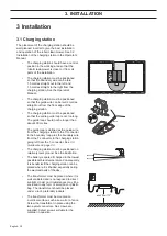
Page 32: ...00 metres The guide loop is defined as the guide wire from the charging station to the T connector in the boundary loop plus the boundary wire from the T connector to the charging station going left from the T connector See 3 3 Guide wire on page 33 The charging station must be positioned on relatively level ground See the illustration The battery is spared if charged in the lowest possible ambien...

Page 33: ... to be installed The robotic lawnmower displays the No loop signal message when an attempt is made to start before the installation is complete It is possible however to test the mower before the installation is completed by doing one of the following Connect a short temporary loop in a small area around the mower Temporarily deactivate the mower s loop detection See 2 6 5 Special settings on page...

Page 34: ...are crossed the robotic lawnmower can interpret that it is outside the working area despite it being inside the working area If the obstacle is also relatively large compared to the working area it may have an impact on the mower inside the entire working area Obstacles within the working area that can be run into should still be demarcated by the boundary wire even though the function of the robo...

Page 35: ...3 6 Installation of guide wire in the Operator s Manual 3 3 1 Installation of the guide wire The position of the charging station and where the guide wire is connected along the boundary loop has an impact on how long the guide loop will be See 1 9 Guide loop on page 12 Make the guide loop as short as possible If the guide loop is longer than 400 metres it may be hard for the mower to follow the w...

Page 36: ...t is recommended to turn off the ECO mode function before carrying out these tests 3 4 1 Test find the charging station The Test find the charging station function allows you to test how well the robotic lawnmower docks safely with the charging station Test find the charging station can only be used after the mower has calibrated the guide wires In other words the mower must have left the charging...

Page 37: ...e position along the guide wire or the boundary loop you wish to test e g on the other side of a narrow passage Also enter How select Right Left along the boundary loop Guide 1 or Guide 2 3 Select Installation Lawn coverage Overview Test Selecting this function causes the mower to follow the selected wire at the maximum distance for the given corridor width 4 Stop the robotic lawnmower after the r...

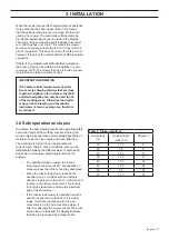
Page 38: ... selected In order to use the robotic lawnmower in the new charging station the new profile must now be selected To give the best function GPS assisted navigation should be disabled for all extra installations and only be used for the main installation 3 7 Even mowing results in complex working areas The robotic lawnmower is equipped with setting options to ensure consistent mowing results even in...

Page 39: ...n on slopes To achieve the best mowing results and operating safety even when parts of the working area are sloping the mower adjusts its operation automatically depending on factors such as the slope angle and travel direction The working area s incline can be expressed in various ways Table 2 Slope conditions sets out the relationship between the different ways of expressing slopes as a percenta...

Page 40: ...ch the PIN code in Husqvarna G2 models does In rare cases there may be a reason to change the loop signal for example if two nearby installations have the same loop signal thereby interfering with each other An option exists to generate a randomly selected new loop signal via the Security New loop signalmenu This also needs to be carried out every time the robotic lawnmower is placed in another ch...

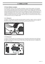
Page 41: ...awn coverage settings In the case of the 330X model certain installations can also be further improved by using two guide wires to give as a result shorter search times However only one guide wire is shown in the examples below 3 10 1 Example 1 In example 1 the charging station is positioned somewhat centrally in the garden A guide wire has been laid through the passage to make it easier to search...

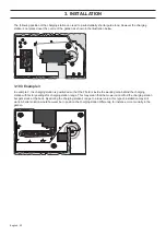
Page 42: ...n is positioned so that the F field is inside the working area behind the charging station with factory settings for charging station range This may mean that the mower cannot find the charging station but gets stuck at the back By altering the charging station s range to a lower value this type of installation may still work A better solution would however be to position the charging station diff...

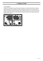
Page 43: ... long search times If a higher corridor width is used instead the mower can take a shortcut and travel through narrow openings and passages to result in shorter search times It is not a problem that the corridor width is set so high to prevent the mower getting through the passage by the guide wire as the mower selects to follow the guide wire when it passes it The mower s search times can therefo...

Page 44: ...Automower 320 and 330X USB cable with a special type of service connector for Husqvarna Automower G2 models e g 220AC 230 ACX Solar Hybrid and 265 ACX 4 1 Installation and login Autocheck EXP can only be installed on PC computers The program has been developed and tested for the following operating systems Windows XP Windows Vista 32 and 64 bits Windows 7 32 and 64 bits and Windows 8 32 and 64 bit...

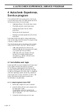
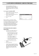
Page 45: ...er software service documents etc It is possible to work with Autocheck EXP without connecting to the Internet for a limited period 4 2 Connection to the robotic lawnmower 1 Connect the service cable between your computer and the robotic lawnmower Remove the protective cover for the battery on the bottom of the mower The service outlet is located beside the main switch Connect the service cable to...

Page 46: ...G3 is selected in the program s bottom left corner If you alternate between mowers from Generation 2 and Generation 3 the channel for the respective family of mowers must be selected When connecting e g Automower 320 and 330X the G3 channel must therefore be selected Remember to refit the protective cover on the service outlet on the mower once work has been completed IMPORTANT INFORMATION Autoche...

Page 47: ...lp texts and illustrations in the program to guide the user The program s main functions are grouped in a number of menus that are accessed via buttons in a list in the upper part of the program Auto test Manual test Operating history Programming Log book Tools Documentation 4 AUTOCHECK EXPERIENCE SERVICE PROGRAM ...

Page 48: ...ice program Auto test is a suitable function to use for an overall review of the components for example in connection with winter service or to start troubleshooting After the review in Auto test the results are presented in a list Non approved results are presented in red while tests that are skipped are presented in yellow Approved tests are indicated by green ticks 4 AUTOCHECK EXPERIENCE SERVIC...

Page 49: ... divided into Key data Search times and Battery capacity Trip is also displayed under Operating data Essentially the same information is saved here as under Key data but with the difference that the trip counter can be reset just as the number of kilometres can be reset in a car This function is ideal to use when you wish to see how the mower has been functioning during a specific period To reset ...

Page 50: ...xt Loading Language is shown in the display Now start Programming in Autocheck EXP Programming a blocked main circuit board If the main circuit board is locked so that it cannot communicate or be programmed in the usual way it can be placed in a so called boot mode This should only be used if the usual programming procedure does not succeed 1 Put the main switch in position 0 2 Connect the USB cab...

Page 51: ...r In Service Mode most functions can be tested and used as normal However there is no access to the security menu in the robotic lawnmower s display It is therefore very important never to return the robotic lawnmower in Service Mode to the customer As long as the main circuit board is in Service Mode the Service mode text flashes in the display 4 3 5 Log book Log book is used to simply save infor...

Page 52: ...ndertaken from this menu include Clear the mower s list of fault messages Restore the mower to factory settings Clear the battery s charging cycle counter recommended when replacing the mower s battery Transfer user settings from log book to new main circuit board Reading the mower s encrypted PIN code the so called security code Transfer PC time to the mower Test the battery s capacity 4 3 7 The ...

Page 53: ...oup with models from 2003 and later Current service plans for many mower models are also here Documents marked in red are newly added and unopened documents On the right in the document tabs is a preview of the first page of selected documents Autocheck EXP automatically searches for new documents when there is a connection to the Internet This means that users can directly access important inform...

Page 54: ... occur at times which make them difficult to find Never touch sensitive electronic components with your fingers for example connectors or components on a circuit board To avoid electrostatic discharge in electronic components always earth yourself for example against a radiator before you start to work on electrical components Always disconnect cables from a component by pulling the connector Do n...

Page 55: ...wer Main circuit board 1 MMI circuit board 2 GPS module not in 320 3 Front loop sensor circuit board 4 Lift sensor circuit board 2 of 5 Collision sensor circuit board 2 of 6 Cutting height sensor circuit board 7 The circuit boards contain the electronics and software required to control the mower s functions In simple terms this can be described as the main circuit board gathering sensor signals t...

Page 56: ...n circuit board in the lower section of the chassis The other sensors are fitted to their own small circuit boards The sensors cannot be repaired If troubleshooting shows that one of the sensors is faulty the entire circuit board depending on which sensor is faulty must be replaced The task of the loop sensors is to measure the signals the circuit board in the charging station sends along the boun...

Page 57: ... The connectors on the circuit boards are marked with text in English that describes which cable is to be connected There are a number of points on the chassis to which the cables can be attached with cable ties We recommend that these fixing points are used at all times It produces a safer installation and reinforces the intuitive feel for where the cable should be connected 5 1 6 Battery The rob...

Page 58: ...s a unit 5 1 9 Charging station Automower 320 and 330X are charged with direct current in contrast to alternating current for the Automower G2 models This means that it is very important to always connect the plus and minus cables correctly to the charging strips on the mower and the contact strips in the charging station 1 The F signal 2 and N signal 3 are generated by two antenna cables that are...

Page 59: ...ront under the mower 3 Pull out the rubber grommet on the charging cable and carefully loosen the connector 4 Loosen the body from the chassis by lifting the body one corner at a time while holding the chassis in place 5 2 2 Disassembling the chassis The chassis consists of upper and lower sections These are screwed together with 14 screws 1 Disassemble the body See 5 2 1 Disassembling the body on...

Page 60: ...ft the display cover so as not to damage the cables connecting the chassis and display cover 5 Disassemble the MMI cable and the sensor cables from the MMI circuit board 5 2 4 Assembling the display cover When assembling Make sure parts are clean and that no cables will be pinched An unsealed chassis can let in moisture which can result in faults in the mower Always use new sealing strips before p...

Page 61: ... let in moisture which can result in faults in the mower Always use new sealing strips before putting the chassis halves or the display cover together A sealing strip that has already been used does not provide a satisfactory seal IMPORTANT INFORMATION 1 Fit a new sealing strip to the lower section of the chassis Automowers 320 and 330X have a 5 millimeter sealing strip unlike for example models 2...

Page 62: ...n the bottom Alternative 2 Counter clockwise Start by laying one end of the sealing strip in line with the marking on the chassis Continue laying the sealing strip counter clockwise around the chassis half Lay the other end of the sealing strip above the first end and then out of the channel Fasten with retainer on the bottom Note that one end of the sealing strip must lie outside the channel on t...

Page 63: ...s for instance about dates or dealer signatures on the guarantee label Always fit the refitted chassis halves with a new guarantee seal The guarantee seal must be included and unbroken for the guarantee to be valid IMPORTANT INFORMATION 5 2 6 Assembling the body 1 Assemble the body on the chassis by pressing the body on top of the chassis s snap on connectors one corner at a time 2 Connect the cha...

Page 64: ...the charging cover forward and upward from the charging tower until the cover comes away from the tower 5 Disconnect the charging cables and the PARK cables only 330X from the main circuit board 6 If the antenna plate must be disconnected from the charging tower the four screws Torx 20 underneath the charging station must be loosened 7 Disconnect the connector with the signal cables from the main ...

Page 65: ...nections on the charging cable are oxidised they should also be replaced 6 Fit the charging strips and the charging cable 7 Fit the holders and then the body 5 6 Replacing the battery 1 Disassemble the body See 5 2 1 Disassembling the body on page 57 2 Disassemble the chassis See 5 2 2 Disassembling the chassis on page 57 3 Loosen the three screws Torx 20 holding the battery cover in place 4 Disco...

Page 66: ...o the correct place 9 Fit the chassis and body Connect the mower to Autocheck EXP and select Programming The service programme will then ask for the mower s serial number Select the correct serial number in the log book Autocheck EXP now automatically transfers the operating information saved in step 1 If the current robotic lawnmower for any reason is not in the log book in Autocheck EXP the seri...

Page 67: ...ard is secured to the display cover by means of two snap on fasteners Carefully bend away the snap on fasteners and lift the MMI circuit board in the edge on which the snap on fasteners are located 6 Remove the MMI circuit board 7 Fit a new MMI circuit board Carefully bend away the snap on fasteners to make it easier to fit the MMI circuit board Only touch the edges of the circuit board Never touc...

Page 68: ...ouch the edges of the circuit board Never touch the board s components and pin terminals IMPORTANT INFORMATION 7 Refit the chassis and body 5 10 Replacing the keypad 1 Disassemble the body See 5 2 1 Disassembling the body on page 57 2 Disassemble the chassis See 5 2 2 Disassembling the chassis on page 57 3 Disassemble the display cover See 5 2 3 Disassembling the display cover on page 58 4 Disconn...

Page 69: ... the display cover Remember to thread the cable through the hole in the display cover Make sure to press the keypad carefully and firmly into position There must not be any loose corners or air bubbles as this can cause dirt and moisture to get in under the keypad 9 Fit the MMI circuit board Carefully bend away the snap on fasteners to facilitate assembly 10 Reconnect all cables to the MMI circuit...

Page 70: ... the body See 5 2 1 Disassembling the body on page 57 2 Disassemble the chassis See 5 2 2 Disassembling the chassis on page 57 3 Disassemble the main circuit board See 5 7 Replacing the main circuit board on page 63 4 Press the snap on fasteners together on the main switch and press the main switch out through the opening in the lower chassis section 5 Fit the new main switch together with the new...

Page 71: ...he front bracket by lifting it straight up still with the display cover closed 4 Clean the filter carefully with a clean and soft brush 5 If damaged the filter must be changed To change the filter 6 a Remove the damaged filter b Clean thoroughly around the mounting surfaces c Apply the new filter ensuring the adhesive surfaces fasten properly to the chassis 7 Refit the bracket by pressing it strai...

Page 72: ...t sensor circuit board and reconnect the cable 6 Refit the chassis and body 5 14 2 Rear loop sensors and tilt sensor The rear loop sensors and tilt sensor are part of the main circuit board The sensors cannot be replaced separately The entire main circuit board must be replaced as one unit See 5 7 Replacing the main circuit board on page 63 5 14 3 Lift sensors The magnet on the collision column mu...

Page 73: ...assemble the body See 5 2 1 Disassembling the body on page 57 2 Disassemble the chassis See 5 2 2 Disassembling the chassis on page 57 3 Disconnect the cable from the collision sensor circuit board Note Always pull the connector and NOT the cable 4 Remove the collision sensor circuit board by carefully bending up the snap on fasteners and lifting out the sensor circuit board 5 Fit the new sensor c...

Page 74: ...ng the chassis on page 57 4 Loosen the connection for the blade motor from the main circuit board and disconnect the cable from the cable brackets in the lower chassis section 5 Dismantle the skid plate four Torx 20 screws the bearing one socket head 4 screw and the blade disc three Torx 20 screws 6 Unscrew the four screws Torx 20 securing the blade motor bracket to the chassis 7 Lift the blade mo...

Page 75: ... and remove the wheel 6 Remove the wheel motor by unscrewing the four screws Torx 20 in the wheel motor bracket 7 Fit the new wheel motor 8 Refit the nut washer wheel and hub cap 9 Connect the wheel motor cable to the main circuit board and attach the cables to the cable brackets 10 Refit the chassis and body 5 17 Replacing the cutting height adjustment motor 1 Disassemble the body See 5 2 1 Disas...

Page 76: ...ght adjustment motor 10 Refit the cogwheel and cover with the motor to the chassis 11 Connect the cable to the cutting height circuit board 12 Refit the chassis and body 13 Calibrate the cutting height adjustment See the Operator s Manual 5 18 Replacing the rear collision columns 1 Disassemble the body See 5 2 1 Disassembling the body on page 57 2 Unscrew the four screws Torx 20 securing the rear ...

Page 77: ...t collision brackets to the chassis 4 Loosen the three screws securing the bracket to the collision column 5 Depending on which part of the collision column bracket is to be replaced a varying amount of disassembly is required By pulling out the split pin using a pliers the collision column can be split to give access to the spring To replace the rubber diaphragm or the inner column the snap on fa...

Page 78: ... Body on page 57 2 Dismantle the front wheel by loosening the three screws on the side of the wheel and then splitting the wheel 3 Remove the lock washer from the axle 4 Remove the washer ball bearing and the inner front wheel half from the axle 5 Apply grease to both ball bearings 6 Refit the inner front wheel half ball bearing and washer 7 Fit a new lock washer onto the axle NB Do not reuse the ...

Page 79: ... recharge or the mower cannot contact the charging station this may be due to worn contact strips in the charging station The contact strips should be replaced when blackened or oxidised Also check the charging strips on the mower See 5 5 Replacing the charging strips on page 63 1 Remove the cover from the charging station See 5 3 Disassembling the charging station on page 62 2 Unscrew the four sc...

Page 80: ...acing the whole part If this is not done a satisfactory seal or function will not be attained To ensure the threads in plastic parts are not damaged 1 Start by carefully turning the screw counter clockwise until it engages the existing threads in the plastic 2 The screw will fall slightly by itself when the threads are located correctly in relation to the existing threads in the plastic 3 Now scre...

Page 81: ... cutting height adjustment Screw grey 4 x 14 mm Torx 20 1 Service plug Screw grey 4 x 14 mm Torx 20 1 Blade motor unit Screw grey 4 x 14 mm Torx 20 1 2 Bracket lift sensor Screw grey 4 x 14 mm Torx 20 2 Front wheel Screw grey 4 x 14 mm Torx 20 1 Front collision column Screw black 5 x 16 mm Torx 20 3 Chassis Screw black 5 x 16 mm Torx 20 1 5 Rear collision column Screw black 5 x 16 mm Torx 20 1 5 W...

Page 82: ... is carried out also perform the following actions 1 Update the main program and the MMI program to the latest version Many problems are solved immediately by the new software When the robotic lawnmower is connected to Autocheck EXP the Assistant notifies if a newer software version is available 2 Reset user settings in the mower by selecting Settings Reset all user settings enter the PIN code and...

Page 83: ...y battery See above See above 30 Battery problem Battery not connected properly Dismantle the mower and check that the batteries are properly connected to their connectors Refer to Replacing the battery on page 63 The main circuit board is faulty The battery on 320 m 2013 can be connected to port B instead of port A on the main circuit board A new main circuit board must be fitted on later model y...

Page 84: ...around the drive wheel Check the drive wheel and remove any objects 25 Cutting system blocked Grass or another object may have become wrapped around the blade disc Check the blade disc and remove any object The blade disc is lying in a pool of water Move the mower and rectify the cause of water collecting in the working area The blade motor is defective Make sure the blade motor has the right spee...

Page 85: ... correctly See Connecting the boundary wire in the Operator s Manual The working area slopes too much at the boundary wire Check that the boundary wire has been laid according to the instructions in chapter 3 Installation in the Operator s Manual The boundary wire is laid in the wrong direction around an island Check that the boundary wire has been laid according to the instructions See chapter 3 ...

Page 86: ...t one this fault message can also appear 55 Difficult finding home The mower has followed the boundary wire but not found the charging station Check the boundary wire s corridor width setting and location refer to the Operator s Manual 56 Guide calibration accomplished Guide wire calibration has been successful No action 57 Guide calibration failed Guide wire calibration has failed Check that the ...

Page 87: ...ng the main circuit board on page 63 38 501 Electronics problem Communication problems between the MMI circuit board and main circuit board Restart the mower by placing the main switch in position 0 wait 10 seconds and then turn the main switch to position 1 Make sure the cable between the MMI circuit board and main circuit board is connected properly Check also that the cable is not damaged pinch...

Page 88: ...on and check that the charging strips and contact strips make good contact 16 Stuck in charging station There is an object in the way of the robotic lawnmower preventing it from leaving the charging station Remove the object The robotic lawnmower slides on the charging station s antenna plate Clean the antenna plate 37 Charging current too high The battery is being charged with too high a current ...

Page 89: ...g See the Operator s Manual The robotic lawnmower vibrates Damaged blade on blade disc Inspect the blades and screws and replace them if necessary Wrong number of blades on the blade disc creates an imbalance Make sure there are no blades missing or that more than one blade is mounted on the same screw The mower mows for shorter periods than usual between charges Grass or a foreign object is block...

Page 90: ...tects the F signal but cannot dock Dirt leaves grass have accumulated in the charging station and are preventing the mower s charging strip from making contact with the charging station s charging strip Clean the charging station N signal from the antenna plate is faulty Check the N signal See 2 6 Tools menu functions on page 23 The cables for the charging strips in the mower are not connected or ...

Page 91: ...y deposits on the charging strips on the mower and the contact strips in the charging station Use an emery cloth and lubricate with a copper paste Also check that the cabling in the charging station and to the mower s charging strip is correctly connected and that they are not damaged The transformer is faulty Check that the mower is receiving the charging power Check that the value for Current co...

Page 92: ...ollow the instructions below 6 4 1 Solid green light The LED in the charging station is solid green but neither the front or rear loop sensor detects any loop signal 1 Generate a new loop signal See 3 9 New loop signal on page 38 The connection between the charging station and the mower is restored Test run the mower and continue with step 2 if the mower still cannot find the loop signal for the l...

Page 93: ...ance in the guide loop using a multimeter The guide loop comprises the guide wire plus the part of the boundary loop that constitutes the return line for the guide signal Disconnect all cables from the charging station during measuring The resistance value for a non faulty guide loop should be between 0 20 Ohm Value 20 Ohm Indicates a break in the boundary loop Identify and repair the break See 6 ...

Page 94: ... not cause disruptions until several weeks or months later To avoid this always select the maximum cutting height the first week after installation and then lower the height one to two steps at a time every week until the desired cutting height has been reached A wire break can be found by using Husqvarna s break detection tool or with the manual method that is described below A description of how...

Page 95: ... LED is flashing yellow in test b then the break is somewhere in the boundary wire between AR and the position where the guide wire is connected to the boundary wire thick black line in illustration B 5 Put all connections back in their original positions Then disconnect AR Connect a new loop wire to AR Connect the other end of this new loop wire somewhere at the centre of the installation If the ...

Page 96: ...tocheck EXP or Tools History total Battery capacity in the mower s display In cases where a battery test cannot be performed on an installation the test can be performed directly on the work bench via Autocheck EXP The test is performed as above except the mower s drive wheel and blade disc rotate freely during the test Since resistance to the drive wheel and blade disc is in principle non existen...

Page 97: ... an incorrect value It is consequently more practical to perform a battery test in connection with the mower s normal operation or in connection with it having recently been in operation When replacing the battery the charging cycle counter should be reset This is done in Tools Reset charging cycle counter in Autocheck EXP This resets the value for Chargings OK which is a measure of how old the ba...

Page 98: ...etween the blade disc and the blades Disassemble the blade disc to enable more thorough cleaning Run the blade motor using the Tools Test Motors Blade motor test function Listen for abnormal sounds when the blade motor is running Also test with various cutting height settings 7 2 Winter storage Before the robotic lawnmower is put away for the winter the following should be done Clean the entire mo...

Page 99: ...he transformer is connected to a mains socket indoors and connected to the charging station the charging station can be left outdoors Otherwise the charging station must be stored indoors If the charging station is stored indoors it is important to remember to protect the ends of the boundary wire from moisture by placing them for example in a coupler from Husqvarna Group 7 MAINTENANCE AND SERVICE...

Page 100: ...acks in the bellows 7 X Open the chassis and change all chassis sealing strips Refer to 5 2 Dismantling and Assembling the Robotic Lawnmower 8 X Change the front collision column rubber bellows Refer to 5 19 Replacing the Front Collision Column 9 X Check tightening torque of chassis screws Refer to 5 2 5 Assembling the Chassis 5 18 Replacing the Rear Collision Columns and 5 19 Replacing the Front ...

Page 101: ...eless due to voltage levels dropping too low Charging the battery fully before winter storage means it does not require maintenance charging during the winter 19 X Study the service messages for any recommended upgrades Updated service bulletins can be found in Autocheck under Documentation refer to 4 3 8 Documentation 7 MAINTENANCE AND SERVICE ...

Page 102: ...AUTOMOWER is a trademark owned by Husqvarna AB Copyright 2014 HUSQVARNA All rights reserved 115 67 74 26 ...

Reviews: