background image

27

TROUBLE SHOOTING

PROBLEM

POSSIBLE CAUSES

ENGINE WILL NOT START.

Blade switch on.
Drive levers not in the neutral slots.
Operator not in seat.
Park brake disengaged.
Dead battery.
Fuel valve closed or in the wrong position.
No fuel.
Spark plugs defective.
Spark plug wires off.

MACHINE WILL NOT MOVE OR MOVES
SLOWLY OR HARD.

Park brake on.
Pump bypass valves open.
Pump drive belt loose or off.
Hydraulic system failure.
Air in the hydraulic system.

BLADES WILL NOT ENGAGE.

Blade belt off.
Clutch unhooked form wiring harness.
Blade switch failure or unhooked from harness.
Fuse burnt out.

UNEVEN CUT

Tire pressure uneven.
Blades bent.
Deck chains uneven.
Deck lift blocks loose.
Anti-scalp rollers set uneven.

CUT IS RAGGED

Blades dull.
Ground speed to fast.
Grass to long.
Grass accumulation under deck.

MACHINE VIBRATION

Blades loose.
Blades unbalanced.
Engine loose from mounts.

Summary of Contents for 968999207 / iZ5223KAA

Page 1: ...nstructions carefully and make sure you understand them before using the machine MANUAL NO 539110842 REV IR 09 08 04 968999254 iZ4217TSKAA 968999255 iZ4817TSKAA 968999256 iZ4821TKAA 968999257 iZ5223TKAA 968999258 iZ5223TKOA 968999259 iZ6123TKAA ...

Page 2: ...2 2004 Husqvarna All right reserved Beatrice NE Printed U S A ...

Page 3: ...hute 16 Adjusting 17 Cutting height 17 Mower deck leveling 17 Throttle lever tension 17 Park brake adj 18 Motion control lever adj 18 OPERATING INSTRUCTIONS 20 Roll Bar and Seat Belt 20 Starting and operation 20 Controls 20 21 MAINTENANCE 22 Engine oil 22 Mower blades 22 Safety interlock system 22 Cutter Housing 22 Hardware 22 Air filter 22 Hydraulic system 23 Deck belt 23 Pump belt 24 Lubrication...

Page 4: ...direction Driving and Transport on Public Roads Check applicable road traffic regulations before driving and transporting on public roads If the machine is transported you should always use approved fastening equipment and ensure that the machine is well anchored Operating This machine is constructed only for mowing grass on lawns and other free and even ground without obstacles such as stones tre...

Page 5: ...ecal affixed to the left side of the frame under the seat The machine s type designation I D The manufacturer s type number Model The machine s serial number Serial no Please state the type designation and serial number when ordering spare parts The engine s manufacturing number is stated on a decal This is placed on the right side on the top of the engine The engine s serial number E NO The engin...

Page 6: ...is a potential for misuse or misassembly R N Reverse Neutral Fast Slow Fuel Ignition Stop Run Start Warning Danger Caution Parking brake Do not stand here Warning Rotating blades keep away from the discharge deck Do not touch rotating parts Battery acid is corrosive explosive and flammable Use on a slope no greater than 10 No passengers Careful going forward watch for other people Careful backing ...

Page 7: ... people maintain a safe distance from the machine Stop the machine if someone enters the work area Clear the area of objects such as stones toys steel wire etc that may become caught in the blades and thrown out Beware of the discharge deck and do not point it at any one Do not use the machine without the discharge deck in place Stop the engine and prevent it from starting before you remove grass ...

Page 8: ...ce it Local laws may regulate the age of the user Engine exhaust and certain vehicle components contain or emit chemi cals considered to cause cancer birth defects or other reproductive system damage The engine ex haust contains carbon monoxide which is colorless poisonous gas Do not use the machine in en closed spaces WARNING WARNING When using the machine approved personal protective equipment s...

Page 9: ...ble Watch out for and avoid driving over furrows holes and bumps On uneven terrain the machine can tip more easily Long grass can hide obstacles Drive slowly Use small movements of the steering controls Be extra cautious with any additional equip ment which can alter the machine s stability Do not mow near verges ditches or banks The machine can suddenly spin around if a wheel goes over the edge o...

Page 10: ...er allow children to operate the machine Be particularly cautious near corners bushes trees or other objects that block your view WARNING The engine must not be started when the driver s floor plate or any protective plate for the mower deck s drive belt is removed Stop the engine Prevent the engine from start ing by removing the ignition key before mak ing any adjustments or performing mainte nan...

Page 11: ... servicing the battery Explo sive gases form in the battery Never perform maintenance on the battery when smoking or near open flames or sparks The battery can explode and cause serious injury damage Ensure that nuts and bolts especially the fas tening bolts for the blade attachments are properly tightened and that the equipment is in good condition Do not modify safety equipment Check regu larly ...

Page 12: ...y and can cause serious crushing injuries Be extra cautious when it is loaded on or unloaded from a vehicle or trailer Use an approved trailer to transport the ma chine Activate the parking brake turn off the fuel supply and fasten the machine with ap proved fastening devices such as bands chains or ropes when transporting Check and abide by local traffic regulations before transporting or driving...

Page 13: ...e drawbar and the thitch points recommended by the mower manufac turer When mower is stopped set brakes securely and use park brake ROPS bar is NOT intended for use in sub zero temperatures If any part of ROPS is damaged the total ROPS MUST BE replaced CHECK ALL BOLTS including seat belt for correct torque before each use Check ROPS structure for damaged before each use Roll Over Protection System...

Page 14: ...ctions and other directions in this manual Lawnmowers and all power equipment can be potentially dangerous if used improperly Safety requires good judgement careful use in accordance with these instructions and com mon sense Motion Control Levers Fuel Cap Key Switch Blade Engagement Switch Park Brake Lever Deck Lift Lever Hour Meter ROPS ...

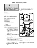
Page 15: ...two per post align the holes in the side post with the frame receiver d Install the 1 2C centerlock nuts finger tight to the side post bolts 3 Install roll bar top loop a Align the holes of the top loop with the left and right side posts b Slide the latch pins thru the front hole on the left and right side to connect the top loop to the side posts and secure with the hairpin c Using 1 2C x 3 1 4 c...

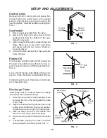
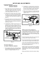
Page 16: ...il type and filling specifications FIG 2 Loosen the discharge chute slightly and lower into position Chute should be snug but still pivot freely Install armrests to seat Hardware and armrests are in the plastic bag Motion Control Lever Control Arm F Full Mark Operating Range FIG 1 FIG 2 FIG 3 Discharge Chute If discharge chute is not assembled to the cutting deck follow the instructions below 1 Ho...

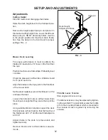
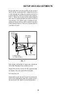
Page 17: ...he blades are at 3 1 2 and the rear blade tips are at 3 3 4 Adjust chains in the slots to remove slack and tighten securely Remove blocks and recheck blade measure ments Adjustments Cutting Height Stop the mower and disengage the blades Raise the deck height lever to the transport posi tion Remove the height adjustment pin and place it in the desired cutting height hole Lower the lift lever down o...

Page 18: ... washers is obtained Check other side for proper ad justment 3 Engage the brake lever and measure the dis tance between the trunnion pin and the collar welded to the brake rod Distance should be 3 16 to 1 4 FIG 5 4 If adjustment is needed loosen the lock nut directly below the yoke Using a wrench ro tate the rod by turning the double nuts using the nuts below the yoke and the nut you just loosened...

Page 19: ...To Adjust Loosen Here Loosen Here Lt Hand Thds Motion Control Lever FIG 7 Begin with either side and put the motion control lever into the neutral position Adjust the motion control linkage by rotating the double nuts in the proper direction until the wheel stops rotating FIG 7 Move the motion control lever forward then into the neutral position and place it into the neutral slot The wheel must be...

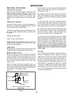
Page 20: ... left control lever Example If control levers are full for ward and the unit turns to the right turn the track ing knob counterclockwise to decrease the speed on the left control lever OPERATION Starting and operation Operator must be sitting in the seat Engage the park brake blades disengaged and the motion control levers in the neutral slots Set choke if needed turn key and release as soon as en...

Page 21: ... to release the brake Key Switch Blade Switch Blade engagement switch located on the console is engaged by pulling up on the switch and pushed down to disengage FIG 9 Choke Control Choke control is located on the console To choke engine pull knob push to release FIG 9 Fuel shut off valve is located at the right rear of the seat The valve has three positions a right tank left tank and center is the...

Page 22: ...ngine manufacturers specifications for cleaning and replacement intervals Safety interlock system Check daily and never operate the machine if the system is not functioning properly The starter should crank only when the operator is in the seat the parking brake is applied blade switch off and the motion control levers in the neutral slots If the machine starts with any of these controls in an ope...

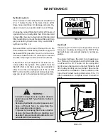
Page 23: ...on then annually after that Drain tank and remove filter be sure to clean around the tank and filter head before removal Replace filter and drain plug and refill hydraulic tank Only use MOBIL 1 synthetic oil FIG 12 Raise and block up the rear of the machine so the drive wheels can rotate freely Start the engine at the lowest RPM possible move the motion con trol levers forward and run machine for ...

Page 24: ...rication See service decal under foot plate for service points and maintenance intervals Clean grease zerks thoroughly before greasing See engine manual for engine service FIG 14 Tire pressure Check every 25 hours All four tires require 15 psi FIG 14 Caster Wheels Check every 200 hours Lift front of unit off of ground so caster wheels can rotate freely Tighten caster bolt then back off 1 2 turn Ch...

Page 25: ...bar 110 Nm 80 ft lb MAINTENANCE Winter storage To prepare the machine for storage Clean the machine especialy under the deck Touch up the paint or spray the underside of deck with a light coat of oil Inspect the machine for damage and loose hard ware Change the oil Drain the fuel system or add stabilizer to fuel Make sure to run the machine after to circulate stabilizer throughout system Remove th...

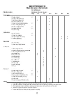
Page 26: ...ntrol shafts X Left and right deck struts X Deck idler arm X Pump idler arm X Caster swivels X Caster tires 5 X Deck lift lever X Throttle cable X Choke cable X Cutter housings X Lift lever X General Check bolts and nuts X Check cutting deck X Clean cutting deck 3 X Clean pump compartment 3 X Check tire pressure 15 psi X Check belts X Check and adjust throttle cable X Notes 1 Change engine oil and...

Page 27: ...e on Pump bypass valves open Pump drive belt loose or off Hydraulic system failure Air in the hydraulic system BLADES WILL NOT ENGAGE Blade belt off Clutch unhooked form wiring harness Blade switch failure or unhooked from harness Fuse burnt out UNEVEN CUT Tire pressure uneven Blades bent Deck chains uneven Deck lift blocks loose Anti scalp rollers set uneven CUT IS RAGGED Blades dull Ground speed...

Page 28: ...28 WIRING DIAGRAMS ...

Page 29: ...29 WIRING DIAGRAMS ...

Page 30: ......

Reviews: